UltraWave Product Guide Page 15
2 Installation
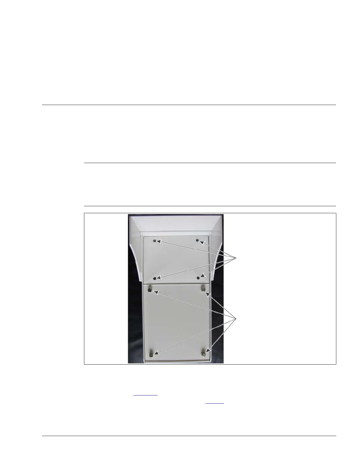
There are two covers on the UltraWave enclosure: the antenna cover and the circuit card cover.
The antenna cover is secured with four inset screws that are factory installed to a finger-tight
torque specification. There are no user-serviceable components in the antenna compartment and
the cover should not be removed for any reason. The circuit card cover is secured with four thumb
screws that are removed to access the circuit card assembly for setup and calibration purposes.
The UltraWave transmitter and receiver units are almost identical, with only minor differences in
component layout. Figure 11
shows an UltraWave receiver and illustrates the unit’s features. The
receiver’s diagnostic activity LEDs are listed in Tab l e 5
.
Note DO NOT remove or tighten the four screws on the antenna
compartment.
To access the transmitter/receiver circuit card assembly, remove
the four screws on the circuit card cover. When replacing the circuit
card cover, tighten the screws until finger-tight. DO NOT over
tighten the circuit card cover screws.
Figure 10 Opening the UltraWave enclosure
DO NOT remove or tighten the 4 screws
on the antenna compartment cover
remove the 4 screws on the circuit card
compartment’s cover to access the circuit
card for setup and calibration