Page 26 UltraWave Product Guide
Silver Network connections
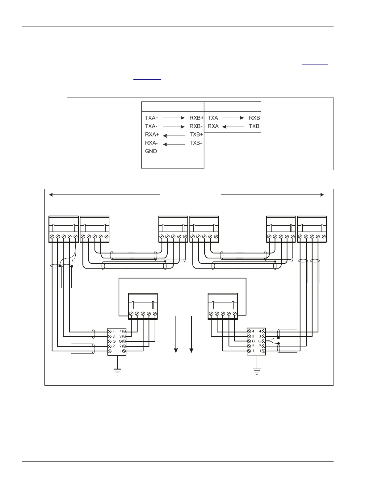
The following connection diagrams illustrate an EIA-422 based Silver Network, a fiber optic based
Silver Network and a mixed media Silver Network using the Silver Loop configuration. Figure 22
shows the network connections and data flow directions for the EIA-422 and fiber optic
communication options. Figure 26:
illustrates an Ethernet based Silver Network using the Star
configuration:
Figure 22 Silver Network connections
Figure 23 Silver Network EIA-422 wiring diagram
EIA-422
Fiber Optic
(use single point
grounding, connect only
one end of shield)
11
223344
55
R
X
B
+
R
X
B
-
G
N
D
T
X
B
+
T
X
B
-
R
X
A
+
R
X
A-
G
N
D
T
X
A+
T
X
A-
11
223344
55
12345 12345
12345 12345
R
X
B
+
R
X
B
-
G
N
D
T
X
B
+
T
X
B
-
R
X
A+
R
X
A
-
G
N
D
T
X
A+
T
X
A-
R
X
B
+
R
X
B
-
G
N
D
T
X
B
+
T
X
B
-
R
X
A+
R
X
A-
G
N
D
T
X
A
+
T
X
A-
R
X
A+
R
X
A-
G
N
D
T
X
A+
T
X
A-
12345
R
X
B
+
R
X
B
-
G
N
D
T
X
B
+
T
X
B
-
12345
maximum 60 devices
max. distance between devices = 1.2 km (3/4 mile)
first receiver second receiver last receiver
shield
shield
shield
shield
shield
shield
NOTE: Use single point grounding - connect one end of the shield, trim the other end and leave it disconnected.
Network Interface Unit
lightning
arrestors
lightning
arrestors
to Network Manager