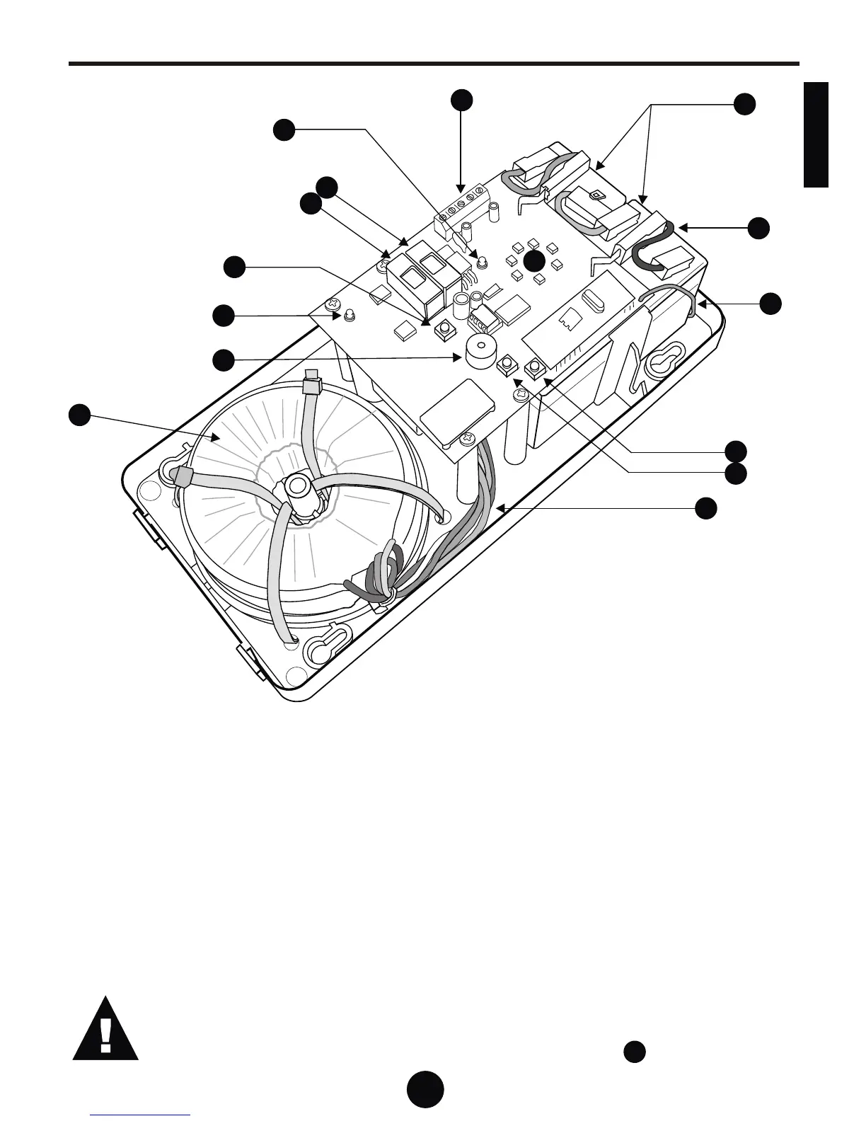
Component Detail - Wall ConsoleComponent Detail - Wall Console
1
2
3
7
8
4
5
6
9
10
11
12
13
14
1. Lead-acid battery (12V 1.3Ah x 2)
2. Battery interconnects
3. Remote receiver antenna lead (BROWN)
4. SET button
5. LEARN button
6. Transformer wiring loom (6 cores terminated onto
Molex connector)
7. Auxillary connection terminals
8. STATUS LED indicator
9. Auxillary supply fuse (1 AMP)
10. Main fuse (5 AMP)
11. TRIGGER button
12. POWER GOOD LED indicator
13. Buzzer
14. Toroidial transformer
15. LED lamp
Shown with cover removed
The product is supplied without the power and interconnecting leads fitted to the
wall console. The leads are to be plugged into the wall console PC board as shown
in the next section.
15
TAKE CARE WHEN REMOVING OR REPLACING THE COVER OF THE
WALL CONSOLE, OR DURING TRANSPORTATION AS DAMAGE
COULD RESULT TO THE LED LAMP
15
LISH
E
N
G
11