28
LISH
E
N
G
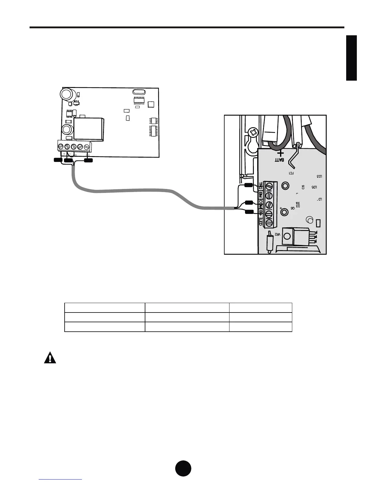
System Commissioning - External RcvrSystem Commissioning - External Rcvr
Connection Diagram for External Receiver
Close up of wall console
Ancillary terminals
External Receiver
GRN
BLK
RED
RED
GRNBLK
Cable: 4 core “comms” cable
Note that the common of the relay contact on the
receiver is connected to the negative terminal of
the receiver, therefore only three wires are
needed.
TRG
COM
B+
Trigger
Common
24V Positive Supply
N/O
- & COM
+ or +12/24
Wall Console Terminal Description Receiver Terminal
Ensure that the receiver you intend to use, can operate from a 24
volt DC supply.