CD MECHANISM SECTION
Perform steps
1,2,
3,4,5
and 10 of the disassembly method to
remove the CD mechanism.
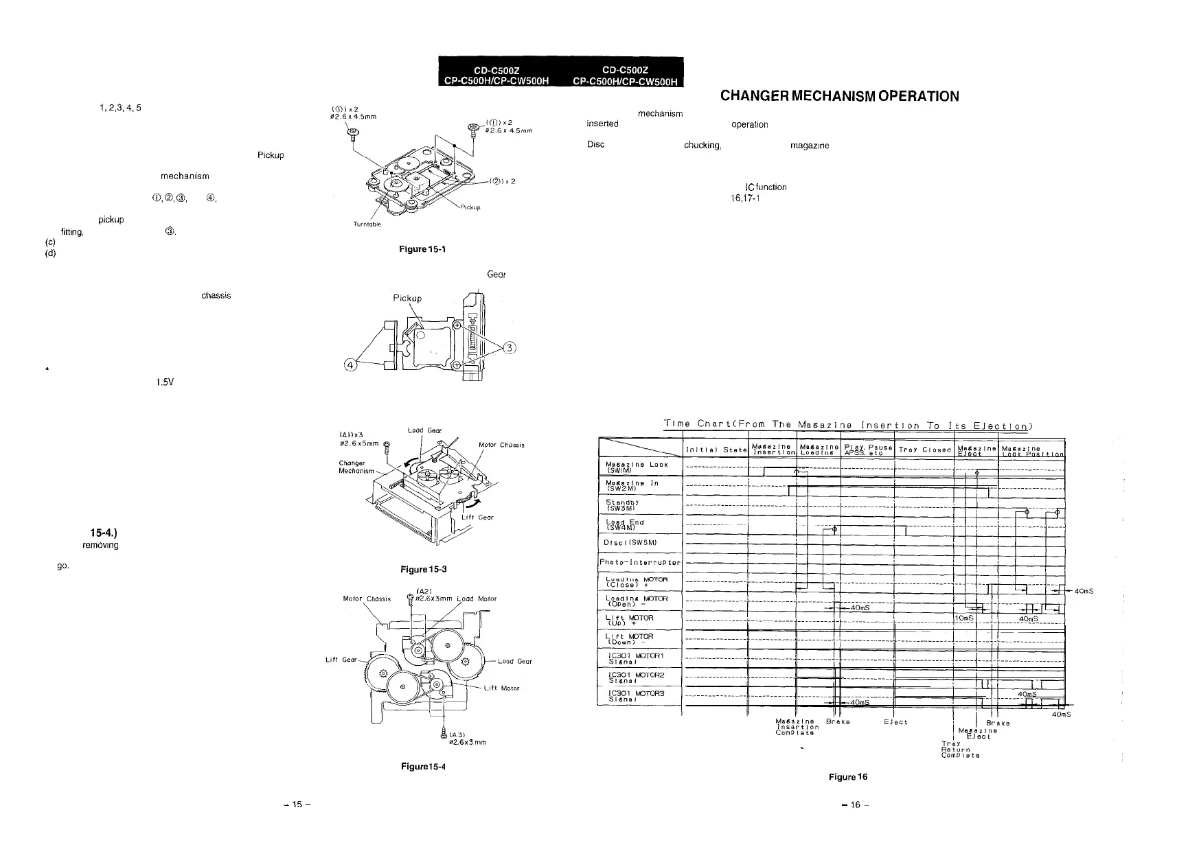
Replacement of pickup (See Figs. 15-1 and
15-2.)
When replacingthe pickup, refer to “Cares when Handling Plckup
Assembly”.
(a) After removing the CD
mechamsm
according to the
disassembling procedure, remove the screws, shafts and
connectors in order of
0,
0,
0,
and
@,
and replace the
pickup.
(b) Fit a new pickup in reverse order of disassembling. After
fittmg,
lock it with the screw
0.
(c)
Connect the connector and lead wire as it was.
(d)
The laser power adjustment is not necessary owing to
improvement of performance of pickup.
Note:
When replacing the pickup do not apply force to the turntable of
spin motor. Otherwise, the height of main chass% and turntable
may be varied.
After replacing the pickup
This new mechanism has been newly designed to enhance
remarkably its performance as compared to the former ones, so
that there is no need to adjust pickup posture.
’
After mounting the pickup. apply voltage to the slide motor, and
ascertain that it runs at DC 1.5V or less.
CD CHANGER MECHANISM SECTION
Removing the CD changer motor (See Figs.
15-3 and
15-4.)
1. Before remowng the motor mounting chassis, turn the load
gear and lift gear in the direction of the arrow as far as it will
go.
2. Remove the 3 chassis screws (Al) which hold the loading
motor and lift motor.
3.
Removethe other 2 screws (A2) which hold the loading motor,
and remove it.
4.
Remove the last 2 screws (A3) which hold the lift motor, and
remove it.
How to remove a CD magazine when it cannot
be ejected (See Fig. 15-3.)
1. If the CD magazine is locked and cannot be ejected due to
trouble, Remove the cabinet, and turn the load gear
counterclockwise manually to eject the CD magazine. (See
Fig 15-3.)
Figure
15-1
Rock
Gear
Figure 15-2
Figure
15-3
CA21
$js2.6x3mm
imld
Molar
I
CHANGER
MECHANISM
OPERATION
This changer mechamsm consists of 6 changers. Magazines are
m%xted by hand, and microcomputer operabon is not
performed.
DISC
tray unloading, disc chuckmg, disc tray storage, magazine
discharge and disc tray selection are performed by the
microcomputer.
1.
For microcomputer operation, see the IC function table.
2. For the timing charts, see Figs.
16,17-i
and 17-2 shown
below.
Figure154
-
15-
Figure
16
-
16-