4
5
6
8 9
-5-
-6-
n
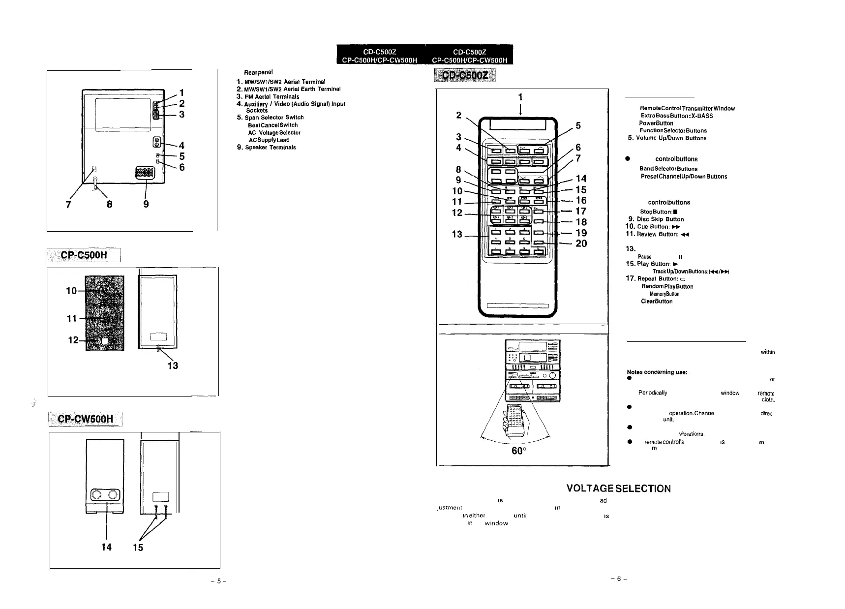
Rear
pane1
‘.
MWlSWllSW2
Asrlal
Terminal
2.
MW/SWl/SWP
Aerial
Earth
Terminal
3.
FM
Aerial
Terminals
4.
Auxiliary
I
Video
(Audio
Signal)
Input
Sockets
5.
Span
Selector
Switch
6.
Beat Cancel Switch
7.
AC
vduge
Sslsctor
6.
AC Supply Lead
9.
Speaker
Terminals
I14
-
15
-
16
-
17
-
18
-
19
-
20
60”
n
Names of controls
1.
Remote
Control
Transmitter
Window
2.
Extra
Sass
Button
:
X-SASS
3.
Power Button
4.
Function Selector Buttons
5.
Volume
Up/Down
Buttons
S
Tuner
control buttons
6.
Band Selector Buttons
7.
Preset
Channel
Up/Down
Buttons
l
CD
control buttons
6.
stop Sutton:
.
9.
Disc
Skip
Button
10.
Cue
Sutton:
H
11.
Review
Sutton:
44
12.
Disc Number Select Buttons
13.
Track Number Select Buttons
14.
Pauss
Button:
I,
15.
Play
Button:
t
16.
Track Up/Down Buttons:
I+
,
m
17.
Repeat
Sutton:
c
16.
Random Play
Sutton
19.
Memory
Button
20.
Clear
Button
q
Proper use of the remote control
Aim the remote control at the remote control sensor
with,”
60” with no obstacles, and operate as shown.
Notes
concsrnlng
uss:
0
Replace the batteries if control distance decreases
or
operation becomes erratic.
l
Periodically clean the transmitter wlndow on the
rsrnote
control and the sensor on the main unit with a soft
cloth.
0
Exposing the sensor on the main unit to strong light can
interfere with ooeration. Chanoe the lighting or the
dlrec.
tion of the
unit:
0
Keep the remote control away from moisture, excessive
heat. shock, and wbratlons.
0
The
remote
control’8
usable range
IS
between 0.2
m
(6”)
and 6
m
(20’) away from the sensor.
VOLTAGE
SELECTION
The voltage selector
IS
located on the rear of the unit. If ad-
]ustment is necessary, use a screwdriver
I”
order to turn the
selector
m
either
direction until the correct voltage figure
IS
displayed
m
the
window
next to the adjustment screw.