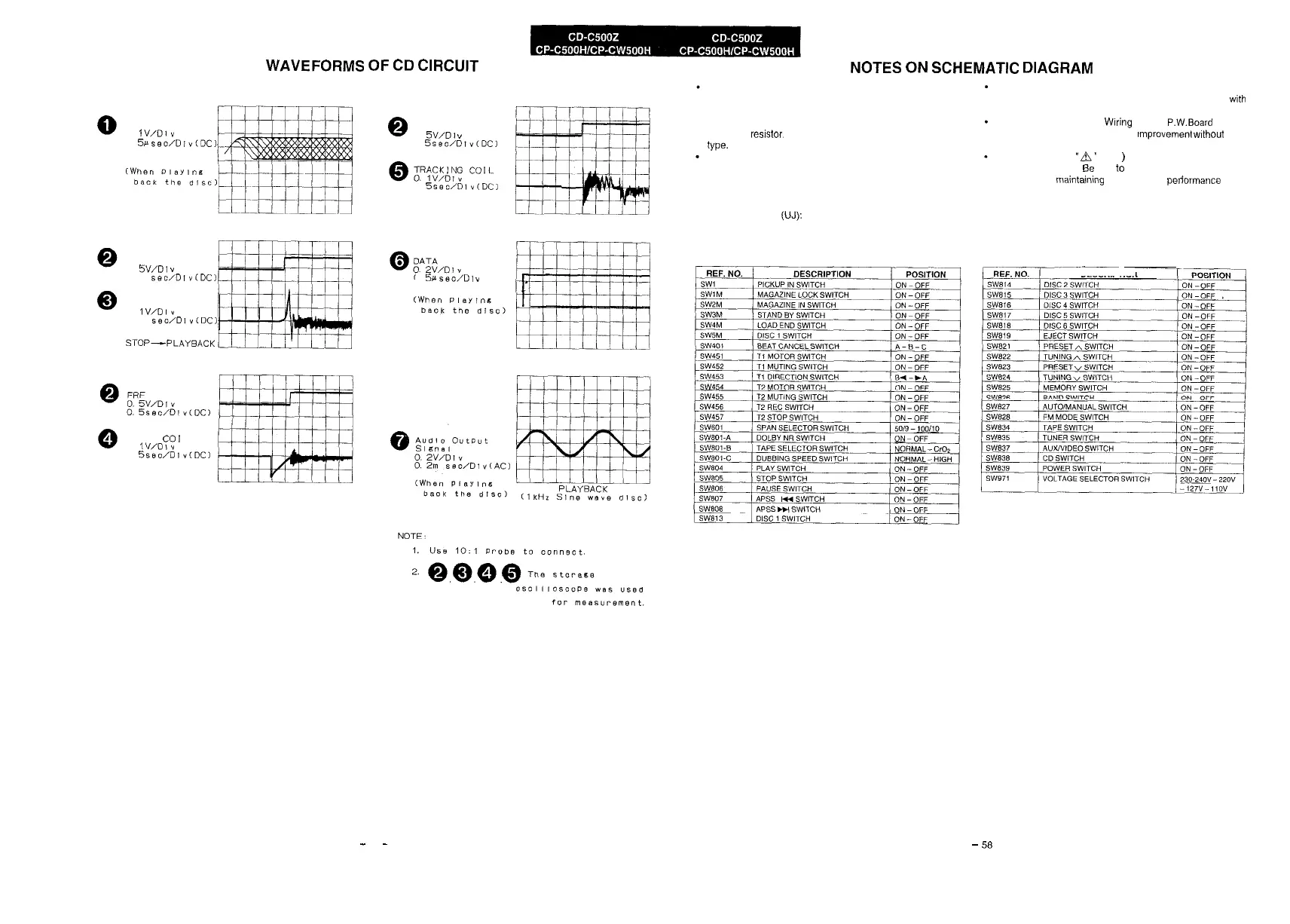
WAVEFORMS
OF
CD
CIRCUIT
NOTES
ON
SCHEMATIC
DIAGRAM
HF
0
lV/OI”
0.
5~seo/lJiv(DC)
FRF
0.
5V/D!
”
50m
sec/D!v(DC)
FE
0
lV/DI”
50m
seo/Di~(DC)
FOCUS
CO1
L
0.
1V/DI”
0
5sec/DIv(DC)
STOP-PLAYBACK
@
FRF
0.
W/D,
Y
0
Sssc/Dlv(DCI
0
5seo/Dl~(DCI
STOP-PLAYBACK
0.
5irseo/D1
v
Resistor:
To differentiate the units of resistors, such symbol as K and
M are used. the symbol K means 1000 ohm and the symbol
M means 1000 kohm and the resistor without any symbol is
ohm-type resistor. Besides, the one with “Fusible” is a fuse
type.
Capacitor:
To indicate the unit of capacitor, a symbol P is used: this sym-
bol P means micro-micro-farad and the unit of the capacitor
without such a symbol is microfarad. As to electrolytic capa-
citor, the expression “capacitance/withstand voltage” is used.
(CH), (TH), (RH), (UJ): Temperature compensation
(ML): Mylar type
(P.P.): Polypropylene type
The indicated voltage in each section is the one measured by
Digital Multimeter betweensuchasectionandthechassis with
no signal given.
Schematic diagram and Wtring Side of P.W.Board for this
model are subject to change for improvement wlthout prior
notice.
Parts marked with
”
A’
(
)
are important for maintaining
the safety of the set. Be sure to replace these parts with spe-
cified ones for maintalnlng the safety and pelformance of the
set.
~~..__
DESCRIPTION
-
57
-
-
58