REMOVING
AND
REINSTALLING
THE MAIN PARTS
TAPE MECHANISM SECTION
Perform steps
1,
2, 3. 4, 5, 6, and 7 of the disassembly method
to remove the tape mechanism.
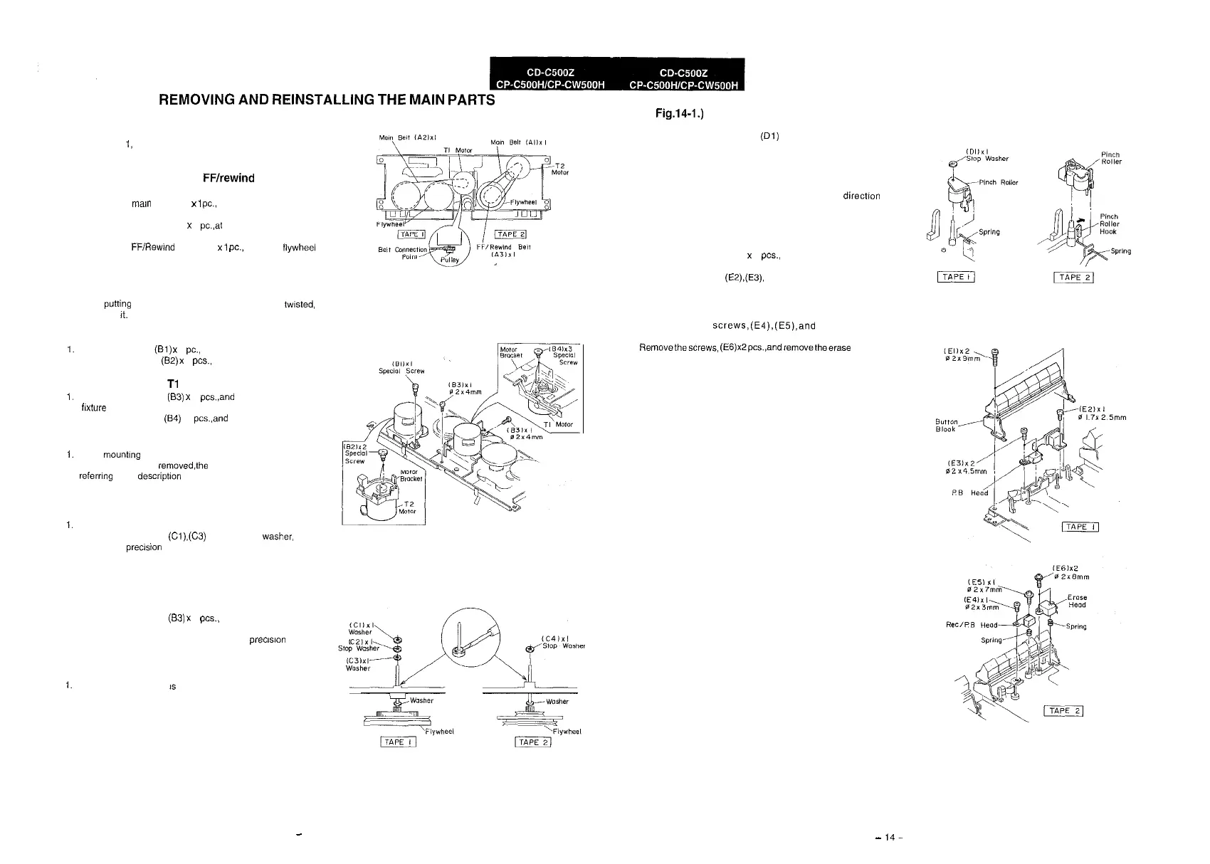
How to remove the main,
FF/rewind
belt (See
Fig. 13-1.)
1. Remove the
Mann
belt, (Al) x
1
PC.,
at the tape 2 side from
the motor pulley.
2.
Remove the main belt, (A2) x 1 pc.,at the tape 1 side from the
motor pulley.
3. Remove the FF/Rewlnd belt, (A3) x
1
PC.,
from the tlywheel
of tape 2.
4.
Put on the belts in the reverse order of removal.
Note:
1.
When putiing on the belt, ascertain that the belt is not busted,
and clean
It.
How to remove the T2 motor (See Fig. 13-2.)
1.
Remove the screw,
(El)
x 1
PC.,
and remove the motor fixture.
2. Remove the screws,
(82)
x 2
PCS.,
and remove the motor.
How to remove the
Tl
motor (See Fig. 13-2.)
1.
Remove the screws, (83) x 2 pcs.,and remove the motor
fc&re
2.
Remove the screws,
(84)
x3 pcs.,and remove the motor.
Note:
1.
When mounting the motor, pay attention to the motor bracket.
2. When the motor is removedShe belt comes off Put it on,
referrlng to the description of belt putting-on.
How to remove the flywheel of tape 1 side (See
Fig. 13-3.)
1.
Remove the drive belt.
2. Remove the washers,
(Cl),(C3)
and the stop wasper, (C2)
with a small precision screwdriver to extract the flywheel from
the chassis.
How to remove the flywheel of tape 2 side. (See
Fig. 1’3-2 and 13-3.)
1.
Remove the drive belt.
2.
Remove the screws, (83) x 2
PCS.,
and remove the motor
fixture.
3.
Remove the stop washer, (C4) with a small precision screw-
driver to extract the flywheel from the chassis.
Note:
1.
When the stop washer
IS
deformed or damaged, replace it
with a new one.
Figure 13-l
Figure 13-2
How to remove the pinch roller of tape 1 side
(See
Fig.l4-1.)
1. Remove the stop washer,
(Dl)
with a small precision
screwdriver, and remove the pinch roller.
How to remove the pinch roller of tape 2 side
(See Fig. 14-l.)
1. Carefully release the pinch roller hook in the
directIon
indicated by the arrow mark, and remove the pinch roller.
How to remove the playback head (See Fig.
14-2.)
1. Remove the screws, (El) x 2
PCS.,
and remove the button
block.
2.
Remove the screws, (EZ),(E3), and remove the head.
How to remove the record/playback and
erase heads (See Fig. 14-2)
1. Remove the
screws,(E4).(E5),and
remove the
record/playback head.
2.
Removethescrews,
(E6)xZpcqandremovetheerase
head.
Be sure to apply screw lock after replacement of head and
azimuth adjustment.
Figure 14-1
Figure 14-2
Figure 13-3
-
13
-
14-