– 15 –
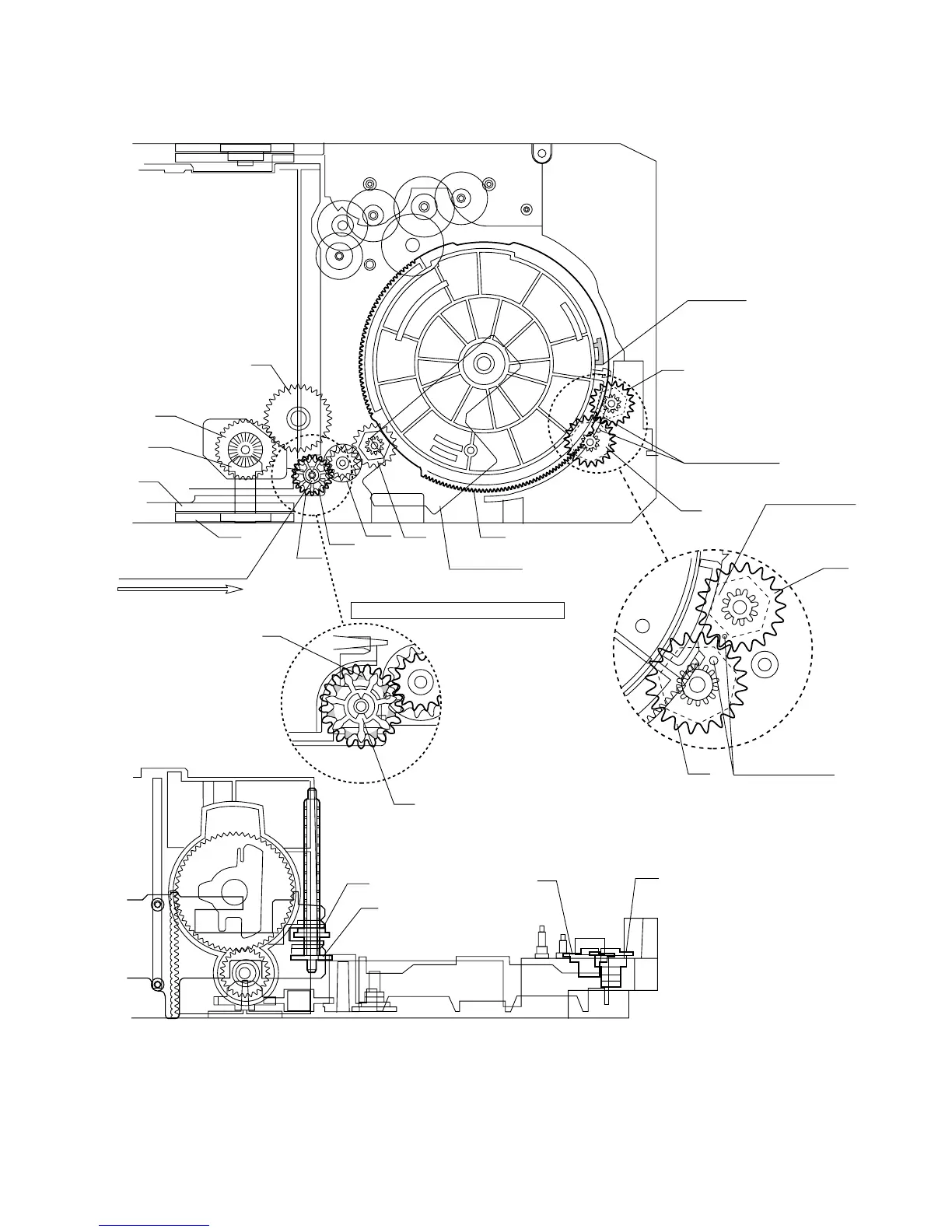
CD-CH1000
131
M T SW PWB
133
TRAY GEAR B
132
TRAY GEAR A
133
TRAY GEAR B
137
132
TRAY GEAR A
138
134
TRAY DRIVE GEAR R
136
TRAY JOINT GEAR R
147
146
134
TRAY DRIVE GEAR R
136
TRAY JOINT GEAR R
110
129
129
123
123
124
125
126
127
Mark position
111
145
TRAY BIG GEAR SET POSITION
133
132
Direct the recess part
(trapezoidal side) of the axis
135 in this direction.
* This position becomes the
reference (stock) position
of the tray.
The hole must align.
It must not rotate in contact
with the peripheral (hatched)
part of 131.
The hole must align.
After assembling 132,
assemble 133.
*1: To position the axis part of 136, engage it with 138.
*2: When it is aligned as described in *1, the hatched part
(low gear-height part of gear) will be positioned in this position.
Note: After positioning the tray big gear in the set position, engage these gears.
*1
*2
Scale: 2 magnifications
Scale: 2 magnifications
Figure 15