ER-A520/A530 Dealer Knowledge Book
Page 224 of 266 Specifications subject to change without notice: Revision date 10/07
Cable & Communications Specifications
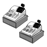
The below diagram represents the cable specification required when connecting the ER-A520 or
ER-A530 model ECR to another same type ECR. The same cable is also used when connecting
to a PC when the 02FD.exe program RAM Data Copy utility is used.
1. Specifications:
(1) Cable: 24-28AWG, Shielded, twisted-pair – (example: Belden no. 8134).
(2) Connector: D-sub 9 pin 9female type) connector.
(3) Baud Rates: 19200, 9600, 4800, 2400, 1200.
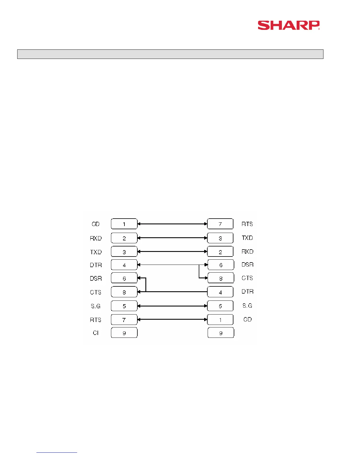
2. Pin Outs:
When connecting the ER-A520/ER-A530 to another ER-ER-A530 or PC, please refer to the
diagram below for the connection pin out diagram.
ECR ECR
9-pin Dsub 9-pin DSub
Note: Pin #9 is not use
SD: Transmitted Data
RD: Received Data
DTR: Data Terminal Ready
DSR: Data Set Ready
RTS: Request to Send
DCD: Data Carrier Detector
CTS: Clear to Send
SG: Signal Ground