15
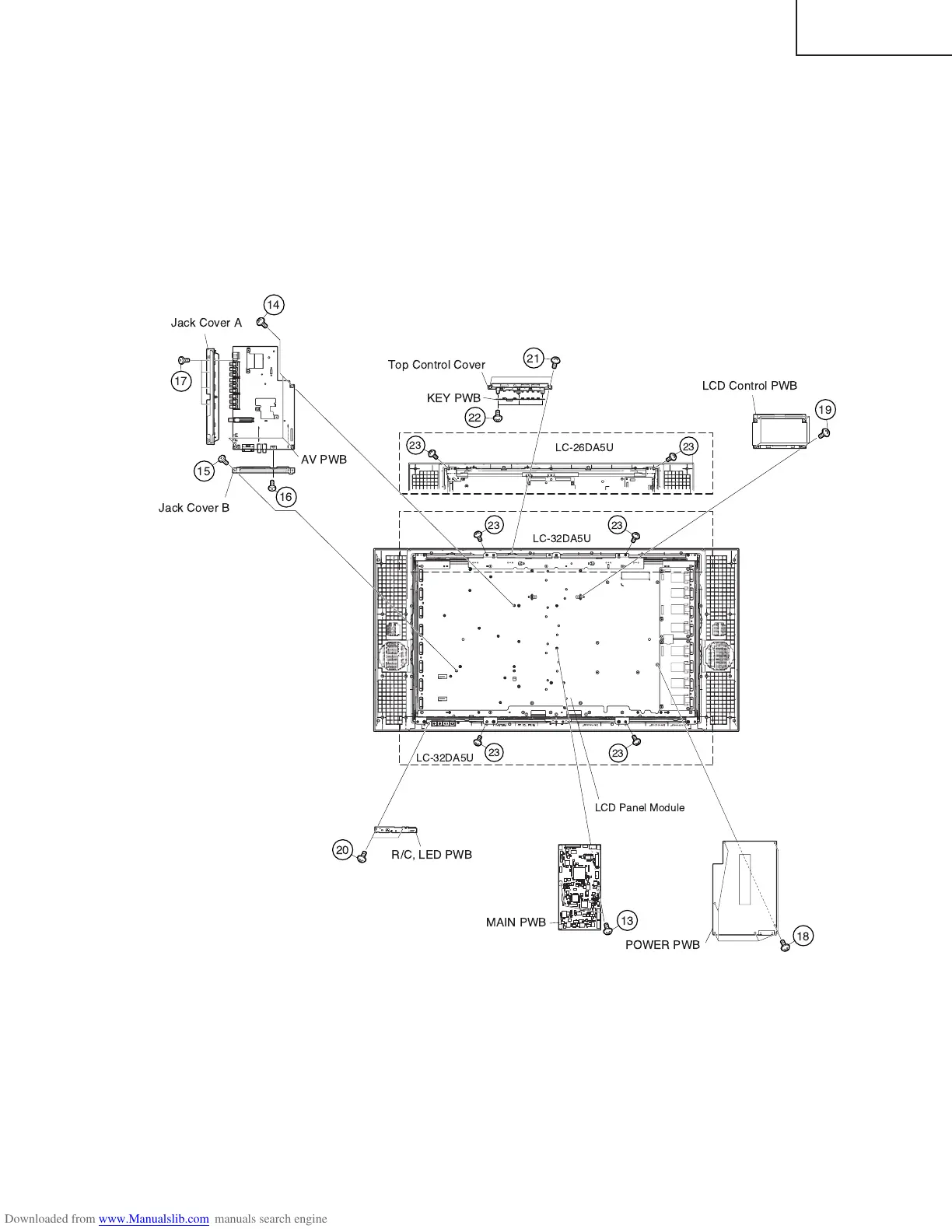
LC-26DA5U
LC-32DA5U
11. Remove the 2 lock screws e and detach the Main PWB.
12. Remove the 3 lock screws r and the 1 lock screw t, and detach the AV PWB. Remove 1 lock screw y and
detach the Jack Cover B. Remove the 4 lock screws u and detach the Jack Cover A.
13. Remove the 6 lock screws i and detach the Power PWB.
14. Remove the 4 lock screws o and detach the LCD Control PWB.
15. Remove the 2 lock screws p and detach the R/C, LED PWB.
16. Remove the KEY PWB.
16-1. Remove the 2 lock screws a from the Top Control Cover.
16-2. Remove the 3 lock screws s from the KEY PWB.
17. Remove the lock screws d (LC-26DA5U:2, LC-32DA5U:4) and take out of the LCD Panel Module.
!"
#
$%& '"
$%& '"
(
)
*+
,- !" '"