21
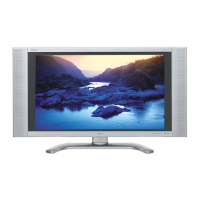
LC-26DA5U
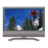
LC-32DA5U
2-3. Video signal adjustment procedure
1) Image adjustment
(1) Device check
■ Before adjustment, make sure that the adjusting device and signal source are set for the Sharp LCD US.
■ Signal generator level adjustment check (Adjustment to the specified level)
» Composite signal : 0.714Vp-p ± 0.02Vp-p (Pedestal to white level)
» 15K component signal : Y level : 0.714Vp-p ± 0.02Vp-p (Pedestal to white level)
PB, PR level
: 0.7Vp-p ± 0.02Vp-p
» 33K component signal : Y level : 0.7Vp-p ± 0.02Vp-p (Pedestal to white level)
PB, PR leve
l: 0.7Vp-p ± 0.02Vp-p
(2) Entering the adjustment process mode
Adjustment item Adjustment conditions Adjustment procedure
1 Adjustment N358 signal
US-10ch
2 Auto adjustment Page 3
performance
Feed the N358 color bar signal (75% color saturation) to VIDEO 1 input.
Feed the RF signal (by use of US-10ch) to TUNER.
Bring the cursor on [ËN358 +TUNER ADJ] and press [ENTER].
[ËN358 +TUNER ADJ OK] appears when finished.
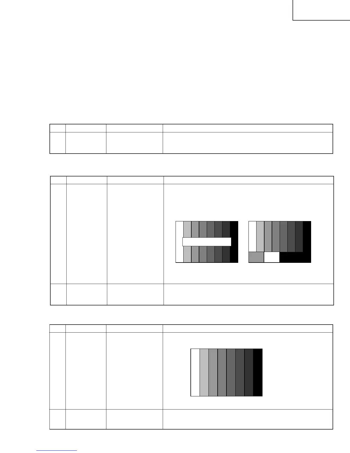
[Video input signal] [US-10CH]
↑100% white ↑100% white
(3) N358 composite signal / Tuner adjustment
Adjustment item Adjustment conditions Adjustment procedure
1 Adjustment
process mode
Enter the process adjustment mode using the process adjustment remote
control.
75% color saturation
↑100% white ↑0% black
Adjustment item Adjustment conditions Adjustment procedure
1 Adjustment 480i signal
2 Auto adjustment Page 5
performance
Feed the 100% color bar signal to Video 1 component input.
Bring the cursor on [ËCOMP 15K ADJ] and press [ENTER].
[ËCOMP 15K ADJ OK] appears when finished.
(4) Component 15K signal adjustment
480i
100% color bar signal