Introduction
Part name
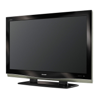
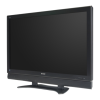
Display (Front view/Side view)
1 2 3 4 5 6 9
10
11
78
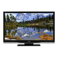
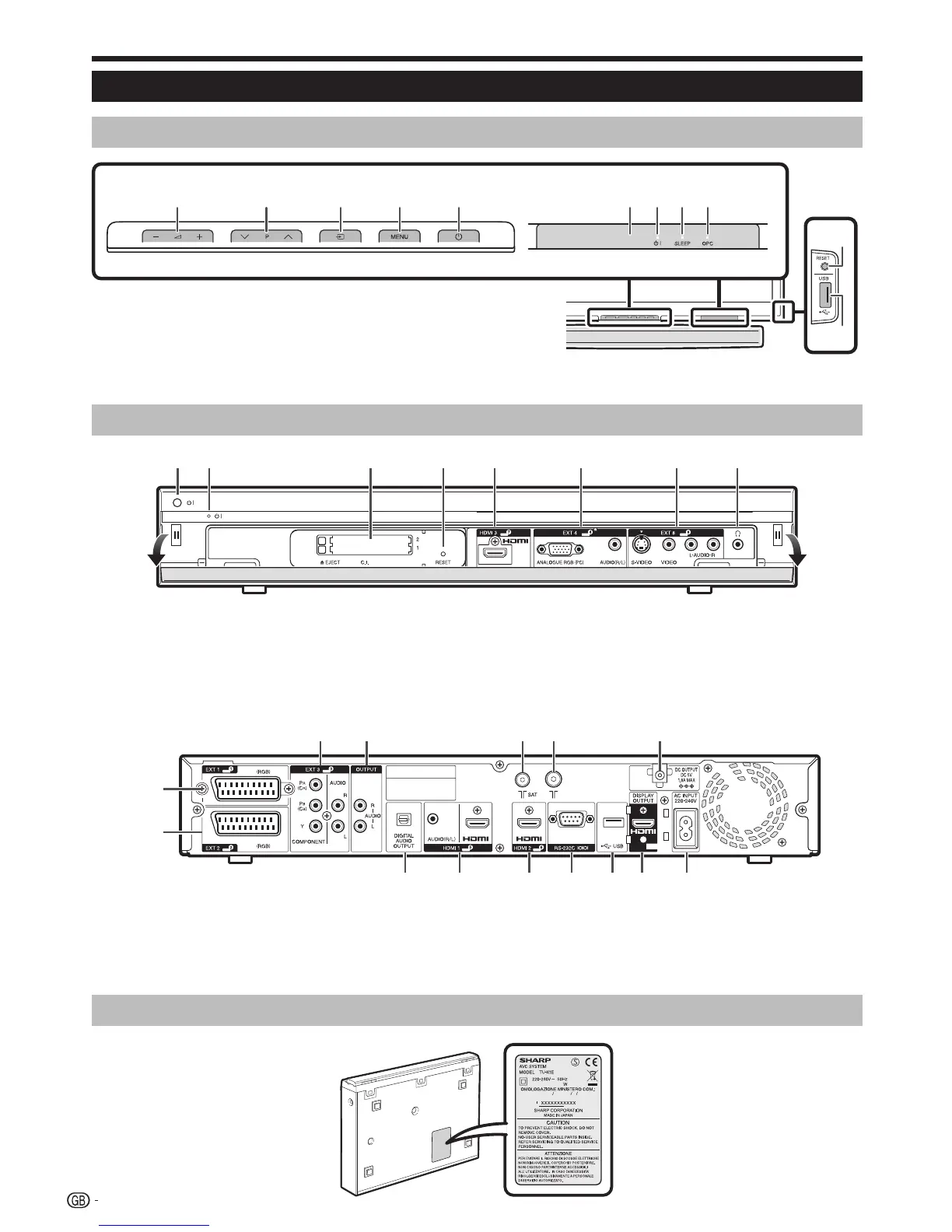
AVC System (Front view/Rear view)
321 4 5 6 7 8
B (Power) button
B (Standby/On) indicator
1
2
COMMON INTERFACE 1/2 slot
RESET button
HDMI3 (HDMI) terminal
3
4
5
EXT4 (ANALOGUE RGB/AUDIO)
terminals
EXT8 terminals
Headphones
6
7
8
WARNING
Excessive sound pressure from earphones and headphones can cause hearing loss.
Do not set the volume at a high level. Hearing experts advise against extended listening at high volume levels.
•
•
AVC System (Bottom view)
11
16
17 18 19 20 21 22
9
10
12 13 14 15
EXT1 (RGB) terminal
EXT2 (RGB) terminal
EXT3 (COMPONENT/AUDIO)
terminals
OUTPUT (AUDIO) terminals
9
10
11
12
SAT (satellite) antenna terminal
Antenna terminal
DC OUTPUT terminal
DIGITAL AUDIO OUTPUT terminal
HDMI1 (HDMI/AUDIO) terminals
13
14
15
16
17
HDMI2 (HDMI) terminal
RS-232C terminal
USB terminal
DISPLAY OUTPUT terminal
AC INPUT terminal
18
19
20
21
22
il/k Volume buttons*
Ps/r Programme (channel)
buttons*
b (INPUT SOURCE) button*
MENU button*
a (Main Power) button*
1
2
3
4
5
Remote control sensor
B (Standby/On) indicator
SLEEP indicator
OPC indicator
RESET button
USB terminal
6
7
8
9
10
11
The symbols light up when pressing these buttons. After a
period of time, the light will turn off.
*
Product label is on the bottom of the
AVC System.
4