LC-90LE740X
4 – 3
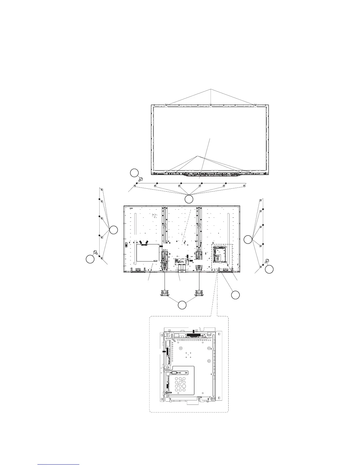
3. Removing of Connectors, 90” LCD Panel Module Unit Ass’y.
1. Disconnect the following connectors from the MAIN Unit. (LV, PD)
2. Disconnect the following connectors from the POWER/DRIVE Unit. (L1, L2, PD)
3. Disconnect the following connectors from the LCD Control Unit. (PL, LV)
4. Remove the 16 lock screws (1) and detach the 16 Module Fix Angles (2)
5. Remove the 7 Hooks and detach the 90” LCD Panel Module Unit Ass’y (3).
6. Detach the 2 Bottom cover (4).
1
2
2
1
1
2
Module
Fix
Angle
Module
Fix
Angle
Module Fix Angle
[PD]
[LV]
MAIN Unit
LCD
Control
Unit
POWER/DRIVE
Unit
Hook
Hook
[L1] [L2]
[PD]
[PD]
[PL]
[LV]
3 90" LCD Panel
Module
Unit Ass'y
MAIN Unit
4Bottom cover