6.
Operation:
1.
Headstock:
a.
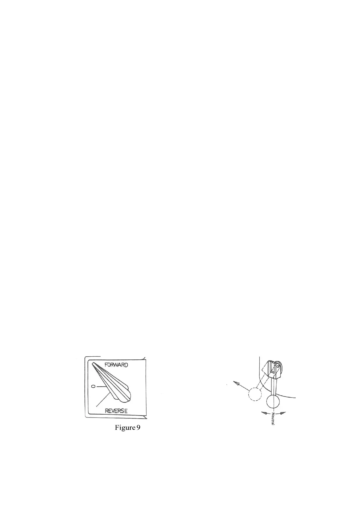
Power to the motor is controlled by a three way switch, forward,
reverse, and off (Fig. 9). When the high-low speed change lever (Fig.
3 (J), Page 3) is in high gear position and the switch is in FOR., the
spindle rotation is clockwise. When the switch is in REV., the rotation
is counter clockwise.
b.
Spindle Brake:
To prevent damage and prolong the life of the brake, the power must
be off and the spindle must be below 200 RPM before engaging brake.
The brake can be engaged by pushing or pulling the brake lever (Fig.
10). Pulling the brake lever up after it is engaged can lock the brake.
Caution: Be sure the brake is in neutral before starting the spindle.
c.
Installation of Collet:
1.
Raise the spindle all the way up.
2.
Insert collet, being sure the keyway lines up with the pin
in the spindle.
3.
To tighten, turn the drawbar clockwise while brake is
engaged. To remove collet, loosen the drawbar (counter
clockwise) three to five turns and tap the drawbar with a soft
mallet to break the collet loose from the taper.
NOTE: When the mill is fitted with the R8 spindle, care must be taken that the collet keyway
is aligned with the pin in the spindle (Fig. 36, page 35).
Brake Setting
Brake Brake
Figure 10