f.
Automatic feed:
Procedure for using this function is:
a. Loosen the quill lock “L” (Fig. 3, Page 3)
b. Place the power feed transmission lever “I” (Fig. 3,
page 3) in the “IN” position.
c. Place feed speed lever “C” (Fig. 3, Page 3) in the
desired position. (H, L, or M).
d. To engage the overload clutch, place feed control lever
“F” to the “F2” position (Fig. 12).
e. The quill will move down when pressing knob “D” (Fig.
11) in, and pulling it out, the quill will go up (The
middle is neutral).
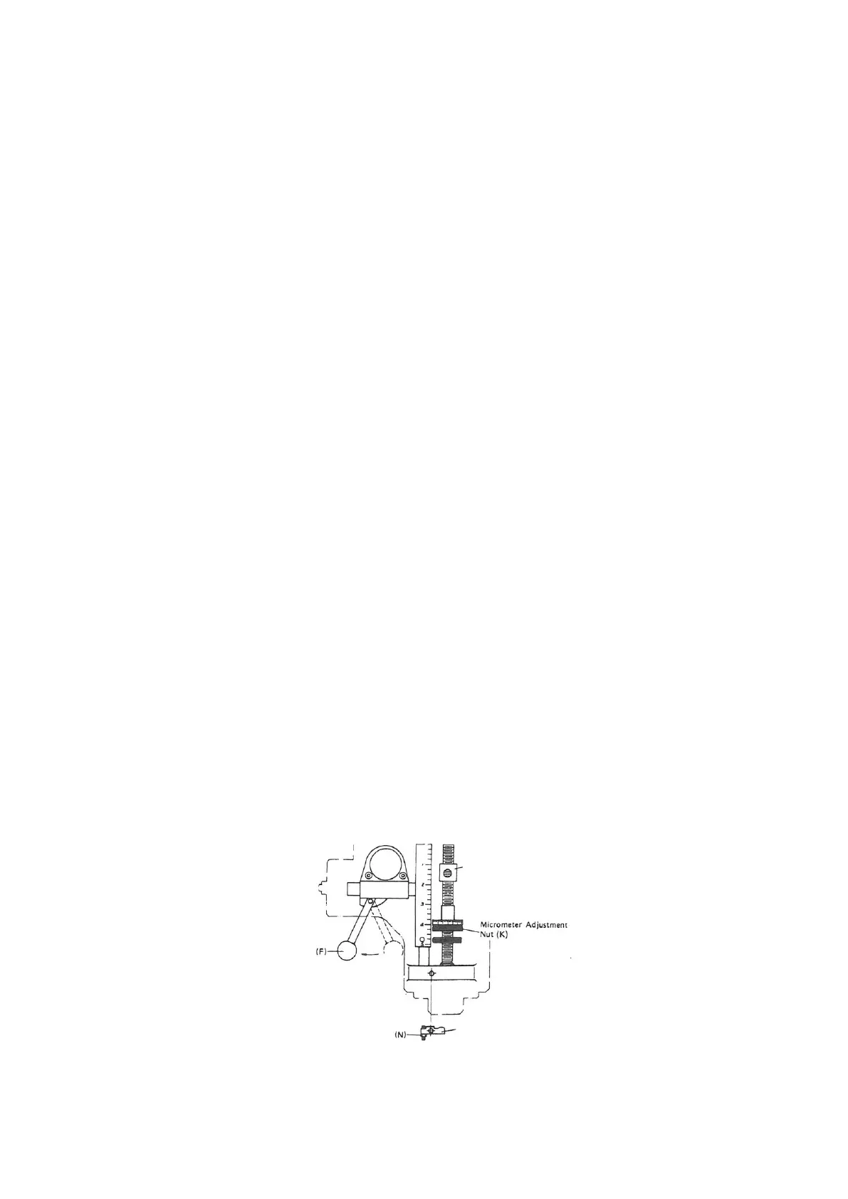
f. The working depth can be set by the use of micrometer
adjustment nut “K” (Fig. 12). This adjusting nut is
graduated in 0.001 and 0.02 mm increments. To activate
the auto feed, pull the feed control lever “F” out. It will
disengage when the adjusting nut contacts the quill stop
block “I” (Fig. 12). For manual trip, you can push the
feed control lever in manually.
Note:
1.
Maximum drilling capacity for automatic feed is 3/8” or 10
mm.
2.
The power feed transmission lever “I” (Fig. 3, Page 3) should
be in the “OUT” position when the power feed is not being
used. To avoid damage to the gears, do not engage the power
feed when the spindle is running.
Quill Stop Block (I)
(F)
F1
Micrometer Adjustment Nut (K)
(M)
(N)
Figure 12