MD-C2
– 18 –
TAPE SECTION
Play:TW-2412 80 g or more
Driving Force Check
Torque Meter Specified Value
Play:TW-2111 30 to 60 g.cm
Fast forward:TW-2231 60 to 120 g.cm
Rewind:TW-2231 60 to 120 g.cm
Checking the playback/FF/rewinding torque
Torque Meter Specified Value
MTT-111 Volume in motor 3,000±30Hz Headphone
Tape Speed
Test Tape
Adjusting Point Specified Value
Instrument Connection
Adjusting the mechanism
ADJUSTMENT
• TEST mode setting method
Holding down the NAME/TOC EDIT key and
key, turn on
POWER key switch. (Or plug in the AC cord.) Frequency is set
in the memory (initial setting) as shown in Table 18. Call the
setting with the JOG DIAL to use it for tuner circuit adjustment
or confirmation.
Preset No. Frequency
P01 87.5 MHz P06 530 kHz
P02 108.0 MHz P07 1,720 kHz
P03 90.0 MHz P08 600 kHz
P04 106.0 MHz P09 1,400 kHz
P05 98.0 MHz P10 990 kHz
Preset No. Frequency
Table 18 Initial setting of memory
• Erasing the registered broadcast station
When the power is off, press and hold the PROGRAM key and
the
key, and then press the POWER key.
All the registered stations are erased.
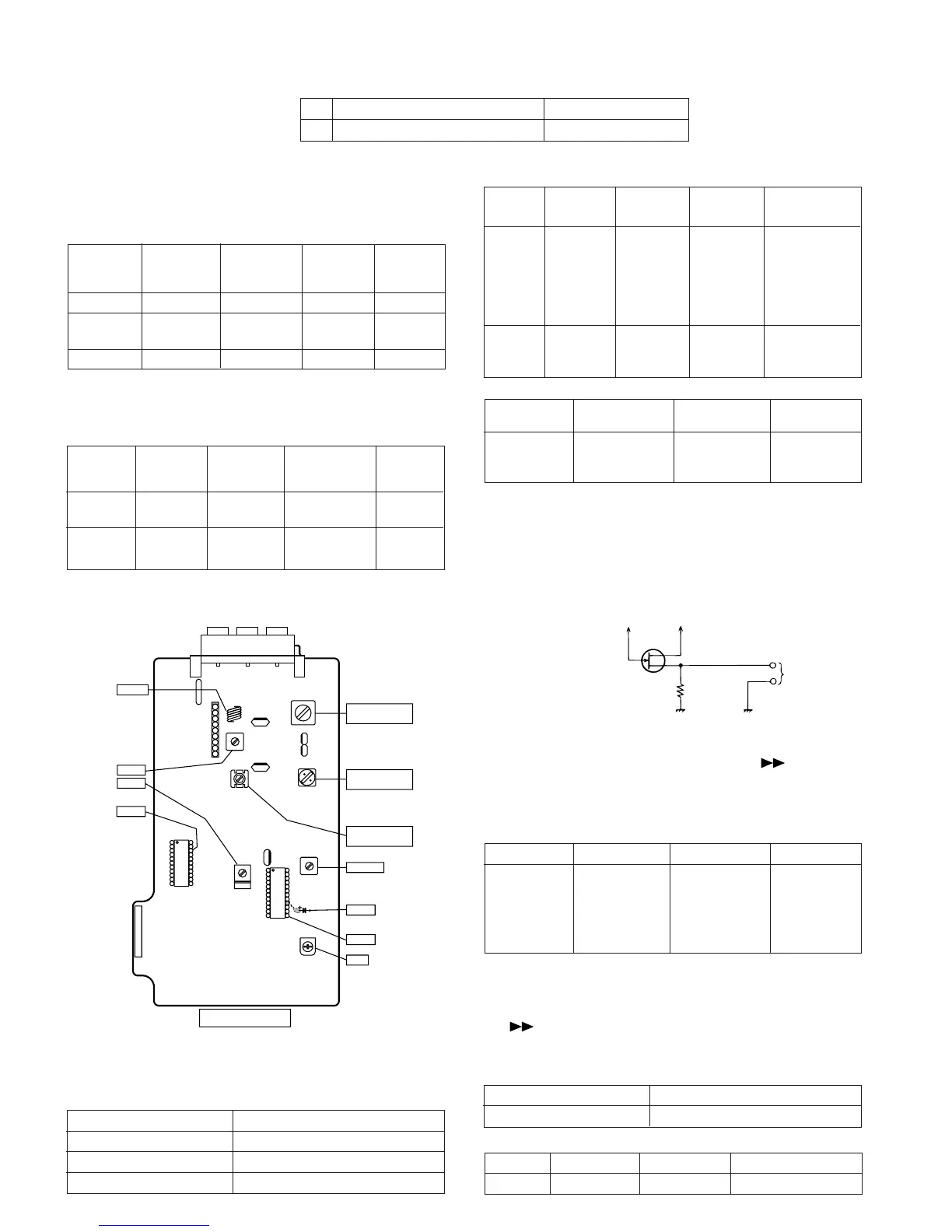
CF301
T351
CF352
T302
T304
VR351
C356
TP301
AM IF
FM DET
FM BAND
COVERAGE fL
AM BAND
COVERAGE fL
AM
TRACKING fL
FM IF
FM RF
TP303
VCO
TUNER PWB
TP302
L303
IC303
VD304
VD303
SO301
T352
T301
L302
IC301
IC302
CNP303
13
16
21
20
1
Figure 18-1 ADJUSTMENT POINT
• AM IF/RF
Signal generator: 400 Hz, 30%, AM modulated
*1. Input: Antenna, Output: TP302
*2. Input: Antenna, Output: TP301
TUNER SECTION
fL: Low-range frequency
fH: High-range frequency
IF 450 kHz 1,720 kHz T351 *1
Band — 530 kHz (fL): T304 *2
Coverage 1.1 ± 0.1 V
Tracking 990 kHz 990 kHz (fL): T302 *1
Test Stage
Frequency Frequency
Display
Setting/
Adjusting
Parts
Instrument
Connection
*1. Input: Antenna, Output: TP301
*2. Input: Antenna, Output: Speaker terminal
• FM RF
Signal generator: 1 kHz, 75 kHz dev., FM modulated
Band — 87.5 MHz L303(fL): *1
Coverage 3.7V ± 0.1V
RF 98.0 MHz 98.0 MHz L302 *2
(10-30 dB)
Test Stage Instrument
Connection
Frequency Frequency
Display
Serring/
Adjusting
Point
• Detection
Signal generator: 10.7 MHz, FM sweep generator
IF 10.7 MHz 98.0 MHz T301(Turn Input: Pin 1 of
the core of IC301
transformer Output: TP302
T352 fully
counter-
clookwise.)
Detection 10.7 MHz 98.0 MHz T352 Input: Pin 1 of
IC303
Output: TP302
Instrument
Connection
Test
Stage
Adjusting
Parts
Frequency
Display
Frequency
Adjusting
Parts
Instrument
Connection
Frequency
Display
Frequency
• VCO Frequency
* Adjust for 76 kHz ± 200 Hz.
Notes:
After preparing the test circuit shown in Fig 18-2, connect the
Pin 13 , Pin 21 and ground of the IC303 with test circuit, and
measure the Value.
At this time, apply a standard unmodulated signal input and
adjust the VCO.
Figure 18-2
98.00 MHz 98.0 MHz VR351* Pin 13, Pin 21
(60 dB) and ground
of IC303
Pin 13 of IC303
TP303
Pin 21 of IC303
D
G
S
10 kΩ
TO FREQUENCY
COUNTER
FET : 2SK19 or 2SK54
Extension Cable (See Fig. 24-6)
Type
Part No.
1 Extension Cable (12 Pin) QCNWK0123AFZZ
When you need to remove the display PWB and main PWB for adjustment, use a prolongation cable for servicing.