MD-C2
– 12 –
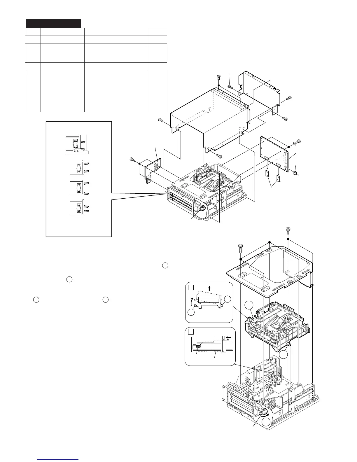
Figure 12-2
How to remove the mechanism block.
(See Fig. 12-2.)
1. Press and hold the hook. Then turn idler gear F A
counterclockwise to slide the lift lever backward.
2. Lift the section
B of the mechanism block first, and remove
it.
Note: To reinstall the mechanism block, push in the section
C first, and then the section B .
1 Shield Case 1. Screw ................ (A1) x7 12-1
2 MD Main PWB 1. Screw ................ (B1) x3 12-1
2. Socket ............... (B2) x1
3. Flat Cable .......... (B3) x2
3
MD Changer Switch PWB
1. Screw ................ (C1) x3 12-1
4 MD Relay PWB 1. Screw ................ (D1) x6 12-2,
/MD Mechanism 2. Screw ................ (D2) x5 13-2,3
(Note 3) 3. Socket ............... (D3) x3
4.
Optical Pickup Flexible PWB ..
(D4) x1
5. Flat Cable .......... (D5) x1
6. Nylon Band ....... (D6) x1
7. Screw ................ (D7) x4
STEP REMOVAL
PROCEDURE
FIGURE
MD-C2 MD UNIT
(D1) x4
ø2 x7mm
Hook
Lift Lever
Idler Gear F
(D1) x2
ø2 x3mm
B
1
A
C
C
B
2
Mechanism
Block
(A1) x1
ø3 x6mm
When installing the MD changer
switch PWB
MD Main PWB
MD Changer
Switch PWB
O.K
N.G
N.G
N.G
(A1) x2
ø3 x6mm
(A1) x1
ø3 x6mm
(A1) x1
ø3 x6mm
(A1) x1
ø3 x6mm
(A1) x1
ø3 x6mm
(C1) x3
ø2 x7mm
(B1) x3
ø2 x5mm
(B3) x2
(B2) x1
Idler Gear F
Turn idler gear F and install the
MD changer switch PWB with
both SW levers A and B in the
lowered position.
Figure 12-1