– 77 –
MD-C2
ICF01 RH-iX0265AW00:System Control Microcomputer (iX0265AW) (1/3)
1 16KHz AN7 Input – – SPEANA input 16kHz
2 4LHz AN6 Input – – SPEANA input 4kHz
3 1KHz AN5 Input – – SPEANA input 1kHz
4 250Hz AN4 Input – – SPEANA input 250kHz
5 63Hz AN3 Input – – SPEANA input 63kHz
6 TUNER-SM AN2 Input – – TUNER signal level detection
7 POSISTOR AN1 Input – –
Temperature detection. Fan "ON" at 0.5V "PROTECT" at 4V.
8 SP-LEVEL AN0 Input – – Output detection. Fan "ON" at 0.5V , "LEVEL" at 3V.
9 CD-SL- PB3 Output H L CD slide motor IN
10 CD-SL+ PB2 Output H L CD Slide motor OUT
11 SY-STB SRDY3 Output – L Sending and receiving data with the display microcomputer.
12 SY-CLK SCK3 Output – L Sending and receiving data with the display microcomputer.
13 SY-COM SO3 Output – L Sending and receiving data with the display microcomputer.
14 SY-DAT SI3 Input – – Sending and receiving data with the display microcomputer.
15 CD-RWC SRDY2 Output – L CD DISP control
16 CD-CQCK SCK2 Output – L CD DISP control
17 CD-COIN SO2 Output – L CD DISP control
18 CD-SQOUT SI2 Input – – CD DISP control
19 DSTB SRDY1 Input – L Sending and receiving data with the MD microcomputer
20 DSCK SCK1 Output – L Sending and receiving data with the MD microcomputer
21 KDATA SO1 Output – L Sending and receiving data with the MD microcomputer
22 MDDATA SI1 Input – – Sending and receiving data with the MD microcomputer
23 CD-DRF P63 Input – – RF detection of a CD , H:A signal is present
24 CD-WRQ P62 Input – – Read request input from CD DISP
25 DISP-RES P61 Output – L Display microcomputer reset
26 MD-ST P60 Output – L MD start control signal
27 MD-RES P47 Output – L MD microcomputer reset
28 CD-RES P46 Output – L CD DSP reset
29 ON/STAND P45 Input – – Start-up signal from the hold mode
30 SERCH P44 Output – L CD search mode notification signal
31 SYS-STOP P43 Input – – Power failure detection input
32 CD-FUNC P42 Output – L CD function : "L", otherwise : "H"
33 TUNER-MUT P41 Output – L –
34 DEMO P40 Input – – Set specification change "L" : C2
35 – RESET Input – – –
36*
– PB0
Output
–L
–
37
Surround ON/OFF
PB1 Output – L
Surround mode : "L"
38 – Xin – – – –
39 – Xout – – – –
40 – Vss – – – –
41 HP-SW P27 Input H – Power amplifier abnormality detected
42 SP PROTECT P26 Input H – Headphone detection SW
43 TUN-SD P25 Input – – Audio processor/TUNER IC control
44 C2-DO P24 Input – – Audio processor/TUNER IC control
45 C2-DI P23 Output – – Audio processor/TUNER IC control
46 C2-SL P22 Output – – Audio processor/TUNER IC control
47 C2-CE P21 Output – L Audio processor/TUNER IC control
48* – P20 – – – –
49 SYS-MUT P17 Output – L –
50* S.W-MUT P16 Output – L –
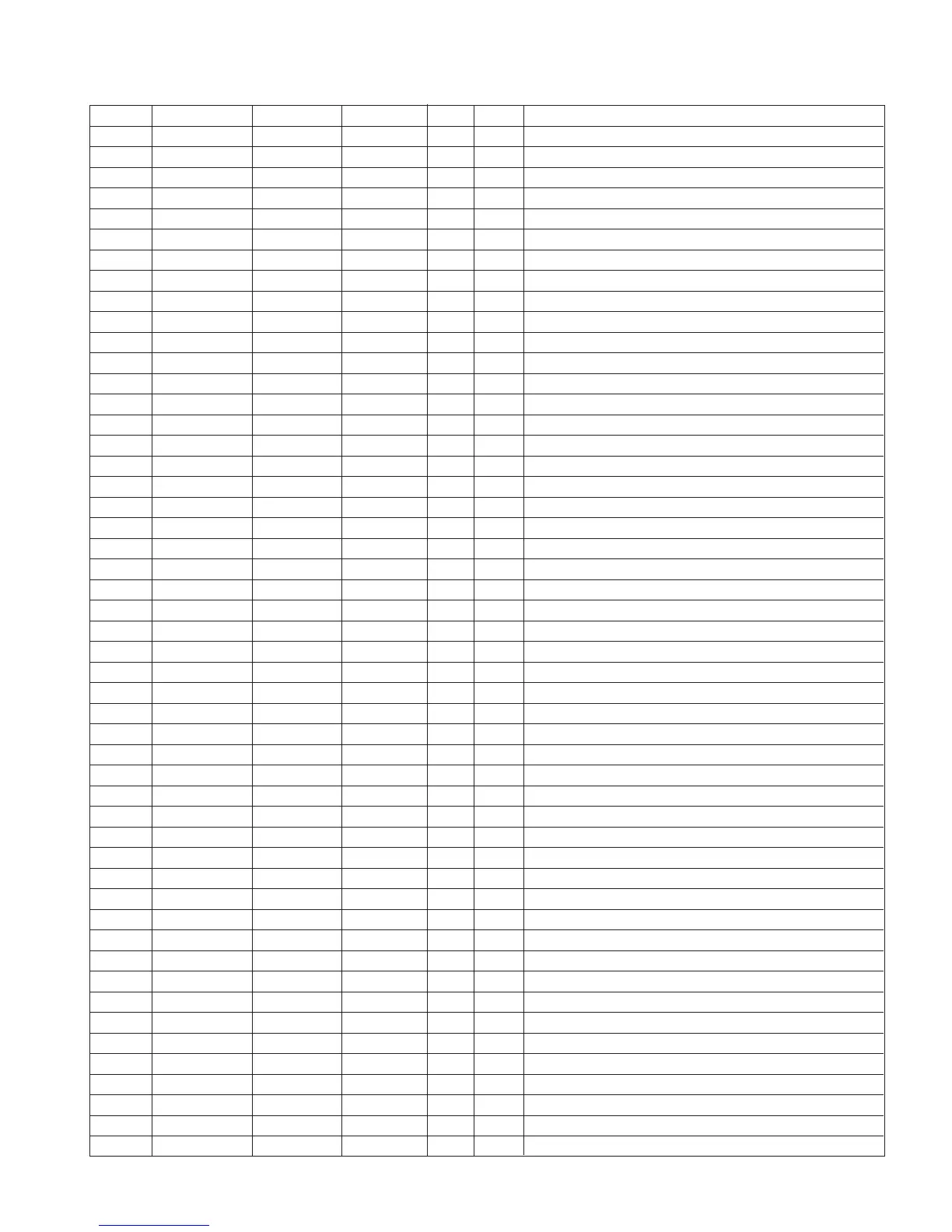
FUNCTION TABLE OF IC
Pin No.
FunctionTerminal Name
Input/Output
Port Name
In this unit, the terminal with asterisk mark (*) is (open) terminal which is not connected to the outside.
Active
Level
Setting
in Reset