– 9 –
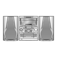
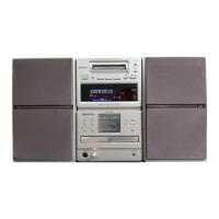
MD-C2
Caution on Disassembly
The disassembling the machine or assembling it after
repair, observe the following instructions so as to ensure
safety and keep its performance.
1. Unload the compact disc, and mini-disc, casette tape
from machine.
2. Be sure to unplug the power cable before starting
disassemble of the machine.
3. When disassembling each section, remove the nylon
band or wire arrangement.
After servicing the unit, be sure to rearrange the leads
where they were before disassembling.
If a screw of improper length is fit to the MD mechanism.
(a screw fit the part to the mechanism chassis of MD
section), it may contact the optical pickup, impeding
normal operation. Hence, due care must be taken.
4. While repairing, pay utmost attention to static electricity
on ICs.
Figure 9-1
Note 1:The CD tray must be opened to remove the CD tray
cover. Open the CD tray using one of the following
methods. After removing the CD tray cover, close the
tray. (See Figure 10-1 and Figure 10-2.)
* Turn the power on and open the CD tray.
* Insert the tip of a screwdriver into the hole
A on the
top of the CD tray. Use the screwdriver to turn the
worm gear 10 turns or more until the lock lever is
released. After releasing the lock lever, manually
push the CD tray out.
* Put the tip of the screwdriver into the hole on the lock
lever through the hole on the back of the CD player
unit. Turn the screwdriver all the way in the direction
indicated by the arrow to release the lock lever. Then,
manually push the CD tray out.
Note 2:When removing or reinstalling the MD unit, avoid a
short circuit by being careful not to allow it to touch the
PWB.
Note 3: After removing the connector for the optical pickup
from the connector wrap the conductive aluminium
foil around the front end of connector so as to protect
the optical pickup from electrostatic damage.
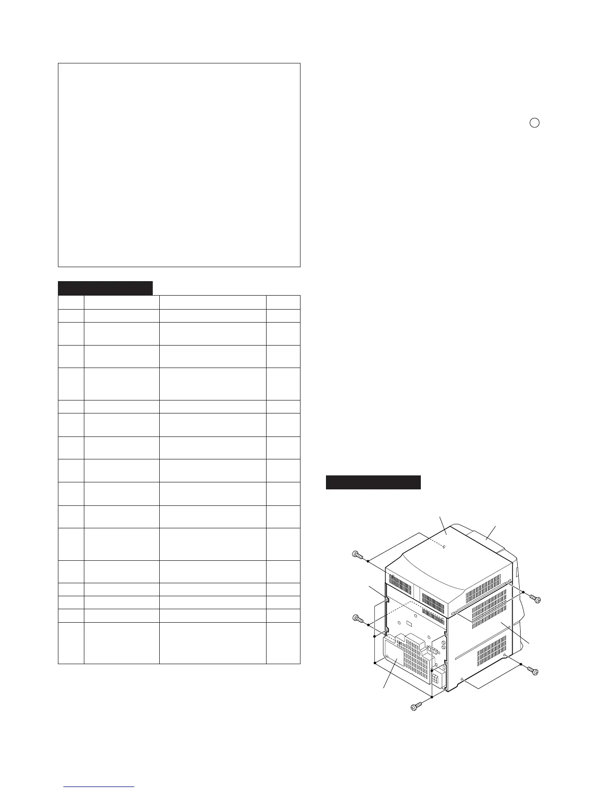
DISASSEMBLY
1 Cabinet 1. Screw ................ (A1) x4 9-1
2 Side Panel 1. Screw ................ (B1) x10 9-1
(Right,Left)
3 CD Tray Cover 1. Hook .................. (C1) x3 10-1
(Note 1)
4 CD Player Unit 1. Screw ................ (D1) x1 10-1
2. Socket ............... (D2) x3
3. Hook .................. (D3) x2
5 Rear Panel 1. Screw ................ (E1) x9 10-1
6 MD Changer Unit 1. Screw ................ (F1) x5 10-3
(Note 2) 2. Flat Cable.......... (F2) x1
7 Power PWB 1. Socket ............... (G1) x2 10-3
2. Screw ................ (G2) x2
8
MD Holder/Fan Motor
1. Screw ................ (H1) x7 10-3
2. Socket ............... (H2) x 1
9 Tuner PWB 1. Screw ................ (J1) x3 10-4
2. Socket ............... (J2) x1
10 Main PWB 1. Socket ............... (K1) x5 10-4
2. Screw ................ (K2) x3
11 Front Panel 1. Screw ................ (L1) x3 10-5
2. Flat Cable.......... (L2) x1
3. Hook .................. (L3) x2
12 Power Amp. PWB 1. Socket ............... (M1) x2 10-5
2. Screw ................ (M2) x4
13 Tape Mechanism 1. Screw ................ (N1) x4 11-1
14 Headphone PWB 1. Screw ................ (P1) x1 11-1
15 Tray Switch PWB 1. Screw ................ (Q1) x4 11-2
16 Display PWB 1. Socket ............... (R1) x1 11-2
2. Knob .................. (R2) x2
3. Nut..................... (R3) x1
4. Screw ................ (R4) x16
STEP
REMOVAL PROCEDURE
FIGURE
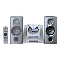
MD-C2 MAIN UNIT
MD-C2 MAIN UNIT
Cares after repairing
After completion of repair of product set the following shipping
mode to return.
1. Make sure that there is not a CD disc in the tray. Press and
hold the PRE-EQ and ENTER buttons, and then press the
RESET switch (or plug in the AC cord) to enter the TEST
mode.
2. After the indication of TEST END appears, unplug the
power cord. If this test mode is executed, the data stored
by the user in the preset memory are all cleared. It is
necessary tell and obtain the consent of user in advance.
(A1) x2
ø3 x12mm
(B1) x2
ø3 x12mm
(B1) x2
ø3 x12mm
(B1) x6
ø3 x12mm
(A1) x2
ø3 x12mm
Cabinet
Front Panel
Rear Panel
Side Panel
(Left)
Side Panel
(Right)