– 87 –
MD-C2
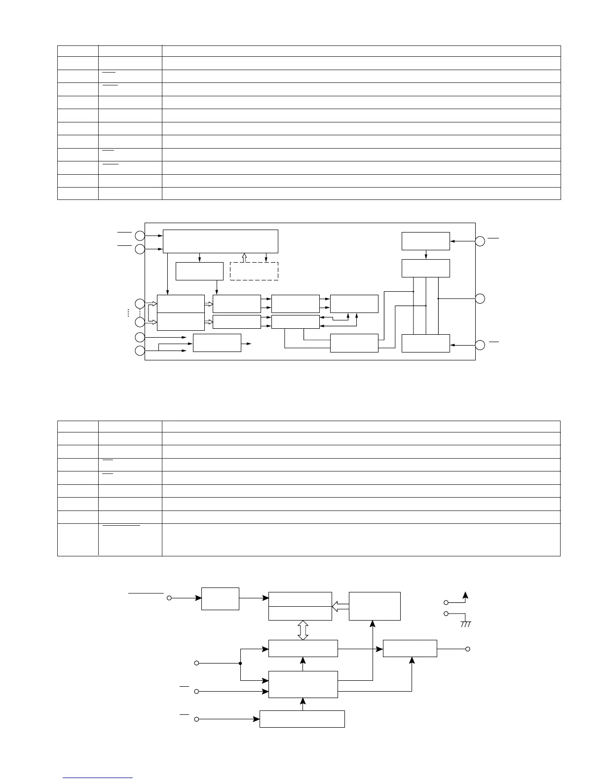
IC1202 RH-iX2474AFZZ: 4bit D-DRAM (iX2474AF)
Pin No.
Function
Terminal Name
1, 2 I/O1, I/O2 Data input/Data output
3 WE Write enable
4 RAS Row address storobe
5 A9 Address input
6-9 A0-A3 Address input
10 Vcc Power (3.3V)
11-15 A4-A8 Address input
16 OE Output enable
17 CAS Column address storobe
18, 19 I/O3, I/O4 Data input/Data output
20 GND Ground
4
RAS
5
17
15
CAS
A0
A9
WE
I/O1~I/O4
20
V
SS
VBB
17
CAS
Clock Generator
CBR Refresh
Counter
Row Address
Buffer
Memory
Cell
I/O
Selection
Write Clock
Generator
Data Input
Buffer
Data Output
Buffer
Row Address
Buffer
On ChipVBB
Generator
Row Decoder
Column Decoder Sense Amp.
Word Driver
SELF Refresh
Timer
MN42V4400 ONLY
3
OE
16
IC1402 VHiS29294A/-1: EEPROM (S29294A)
Pin No.
Function
Terminal Name
1* NC Not connected
2 Vcc Power
3 CS Chip selection input
4 SK Serial clock input
5 DI Serial data input
6 DO Serial data output
7 GND Ground
8 PROTECT Memory protection input
Connected to GND or open : Protection valid
Connected to VCC : Protection invalid
PROTECT
write-
protection
circuit
Memory array
Data register
Output buffer
Clock generating circuit
Mode decode
logic
Address
decoder
Bank 1
Bank 2
Vcc
GND
DO
DI
CS
SK
In this unit, the terminal with asterisk mark (*) is (open) terminal which is not connected to the outside.
In this unit, the terminal with asterisk mark (*) is (open) terminal which is not connected to the outside.
Figure 87-1 BLOCK DIAGRAM OF IC
Figure 87-2 BLOCK DIAGRAM OF IC