Do you have a question about the Sharp MX-C250F and is the answer not in the manual?
Describes the overall system components and their interconnections.
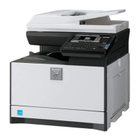
Lists the available models and their configurations across different regions.
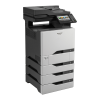
Details optional accessories and their compatibility with machine models.
Covers fundamental engine, copy, printer, and scanner/FAX specifications.
Details the printing speeds for various paper sizes and trays.
Specifies the maximum printable dimensions for different paper types and sizes.
Lists the scanning and printing resolutions supported by the machine.
Outlines scanner capabilities including resolution and gradation for copying and transmission.
Describes the first copy time and job speed for copy operations.
Details supported operating systems and driver compatibility for printing.
Explains transmission methods, support lines, and image quality processes for scanning and faxing.
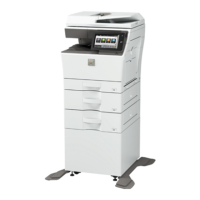
Covers paper handling capabilities for main unit, optional drawers, and bypass tray.
Details paper ejection capacities and specifications for duplex and exit trays.
Lists consumable parts and their quantities by region.
Details maintenance parts and their replacement intervals by region.
Explains how the end of life for developer and drum cartridges is determined.
Explains how to identify production numbers on toner and developing units.
Specifies the standard and usage environmental conditions for the machine.
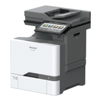
Provides a labeled diagram identifying external components and their functions.
Explains the function and operation of the document feeder and glass.
Details the function of each key and indicator on the operation panel.
Lists the functions of the operation panel keys and indicators for USA models.
Describes the rollers and detectors within the Single Pass Feeder (SPF) unit.
Details the rollers and detectors within the Reversing Single Pass Feeder (RSPF) unit.
Lists various sensors and detectors and their functions within the machine.
Identifies and explains the function of key switches like main power and door switches.
Lists and describes the function of various clutches and solenoids controlling paper transport.
Identifies the motors and their specific functions within the machine's operation.
Details the various rollers and their functions in paper transport and fusing.
Lists the lamps used in the machine and their functions, such as fusing and discharge.
Identifies cooling fans and ozone filters and their roles in machine operation.
Lists the main Printed Wiring Boards (PWBs) and their functions in controlling machine operations.
Details the location and specifications of fuses and thermostats for protection.
Provides general guidelines for performing adjustments and their importance.
Lists all adjustable items with their corresponding job numbers and simulation codes.
Provides step-by-step instructions for specific adjustment procedures.
Explains the purpose and basic operations of the simulation mode.
Provides a comprehensive list of simulation codes, their functions, and relevant sections.
Offers specific operational procedures for various simulation codes.
Details the soft switch settings for FAX-related functions and their parameters.
Explains how the machine detects and displays errors, and the general troubleshooting approach.
Lists JAM codes, their causes, and troubleshooting steps for paper jams.
Details the communication report codes for image send functions and their meanings.
Discusses dial tone detection settings and confirms proper operation.
Outlines the cases requiring ROM update and notes for the process.
Provides instructions for updating firmware using USB memory.
Covers essential maintenance tasks like counter resets and initial settings.
Explains how to perform the initial setting for toner density after replacing cartridges.
Guides the user through the auto color calibration process when specific parts are replaced.
Lists other maintenance items such as skew adjustment and firmware version checks.
Provides instructions for disassembling external units and covers.
Details the procedures for disassembling and reassembling internal units like PWBs and operation panel.
Explains the structure and basic operation of the machine's control panel.
Describes the operational functions of the Single Pass Feeder (SPF) and Reversing Single Pass Feeder (RSPF) units.
Details the electrical and mechanism aspects of the scanner unit's operation.
Explains the electrical and mechanism components of the manual paper feed section.
Describes the electrical and mechanism relation diagram of the paper registration section.
Details the electrical and mechanism relation diagram of the paper feed tray section.
Explains the electrical and mechanism relation diagram of the paper exit section.
Describes the electrical and mechanism relation diagram of the duplex section.
Explains the electrical and mechanism relation diagram of the LSU section.
Details the electrical and mechanism relation diagram of the OPC drum section.
Explains the electrical and mechanism relation diagram of the toner supply section.
Details the electrical and mechanism relation diagram of the developing section.
Explains the electrical and mechanism relation diagram of the transfer section.
Describes the electrical and mechanism relation diagram of the fusing section.
Identifies the fans and filters and their functions in cooling and air purification.
Presents the overall system block diagram showing interconnections of major components.
Illustrates the AC and DC power supply lines and their connections.
Shows detailed wiring connections between the MFPC, LSU, FAX, and USB components.
Provides a comprehensive list of signals, their descriptions, connector and pin numbers, and PWB location.
Outlines the workflow and precautions for replacing main PWBs and the HDD.
Lists essential tools and their part codes required for servicing the machine.
| Functions | Print, Copy, Scan, Fax |
|---|---|
| Print Resolution | 600 x 600 dpi |
| Copy Resolution | 600 x 600 dpi |
| Scan Resolution | 600 x 600 dpi |
| Fax Modem Speed | 33.6 Kbps |
| Max Paper Size | A4 |
| Operating System Compatibility | Windows, macOS, Linux |
| Type | Laser |
| Print Speed | 25 pages per minute |
| Copy Speed | 25 cpm (A4) |
| Paper Capacity | 250 sheets |
| Paper Size | A4, A5, B5, Letter, Legal |
| Duplex Printing | Yes |
| Connectivity | USB, Wi-Fi |
| Display | LCD |