MX-C250 OPERATIONAL DESCRIPTIONS 11 – 11
7. Paper exit section
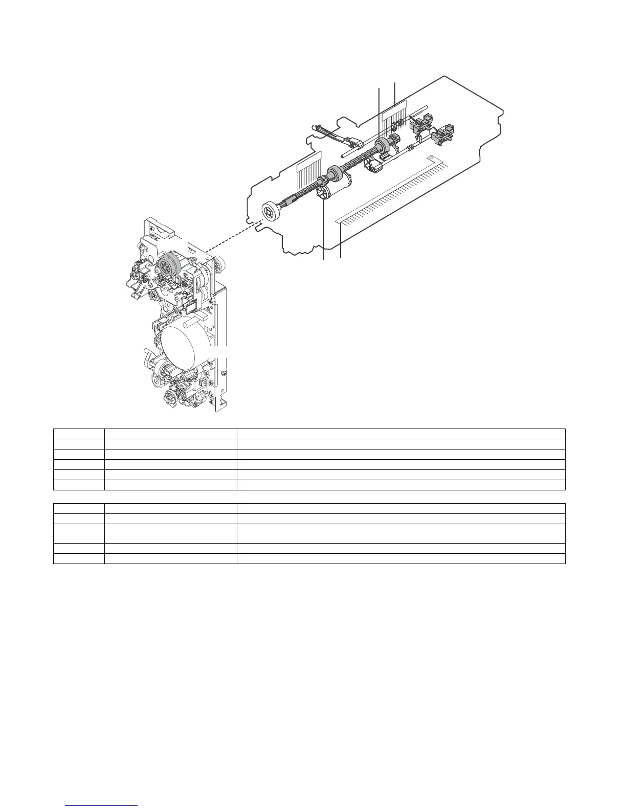
A. Electrical and mechanism relation diagram
B. Paper exit operation
The fuser motor drives the paper exit clutch which drives the paper
exit roller. The paper exit roller along with pressure from the paper
exit idle rollers drive the paper into the paper exit tray.
C. Switchback operation
In duplex mode, POD1 detects the lead edge of the paper from the
fuser section. After a specific amount of time, dependant on paper
size, the paper exit clutch is turned off and the paper exit reverse
clutch is turned on reversing the direction of the paper into the
duplex paper path for transfer of image onto side two of the paper.
Signal name Name Function and operation
FUM Fusing drive motor Drives the fusing unit, the paper feed section and Registration sections.
POD1 Paper exit detector 1 Detects paper pass in the paper exit section. Detects a paper jam.
POC Paper exit clutch Controls the drive timing of paper exit roller (drive).
POD2 Paper exit detector 2 Detects paper pass in the paper exit section. Detects a paper jam.
TFD Paper exit tray full detector Detects paper full in the paper exit tray.
No. Name Function and operation
1 Paper exit roller (drive) To exit paper onto the exit tray and perform switch back operations when in duplex mode.
2 Paper exit roller (idle) To apply pressure to a paper with the paper exit roller (Drive), to give a feeding force of the exit roller to
a paper.
3 Discharge Brush1 To discharge static generated in the fuser section.
4 Discharge Brush2 To discharge static generated in the paper exit section.