Now an appropriate PIC-burner circuit for the 11-pin interface of the PC-G850V(S) is
needed, that utilizes the integrated PIC-loader and supports the PIC16F8x
microcontroller family. Such a circuit must match the follwing criteria at least:
1. The CP-signal must control the programming/burning voltage for the PIC.
2. DATAIN and DATAOUT must be interconnected already for the connection-test
phase.
3. The inverted CLK#-signal must be provided at the RB6-pin of the PIC.
4. The CLK#-signal is very sensitive for cross-talk – especially from DATOUT.
Shielding and/or elemination of interference can be necessary. Furthermore a
pulldown resistor is needed for a defined LOW-level of the CLK#-signal.
5. The LOWBATT# input must either be connected to a programming voltage
monitoring circuit or pulled up to the HIGH-level.
The following circuit meets these requirements. An additional feature is that it does not
need an external power supply providing the programming voltage, but it creates this via
a DC/DC-converter from VDD (+5V):
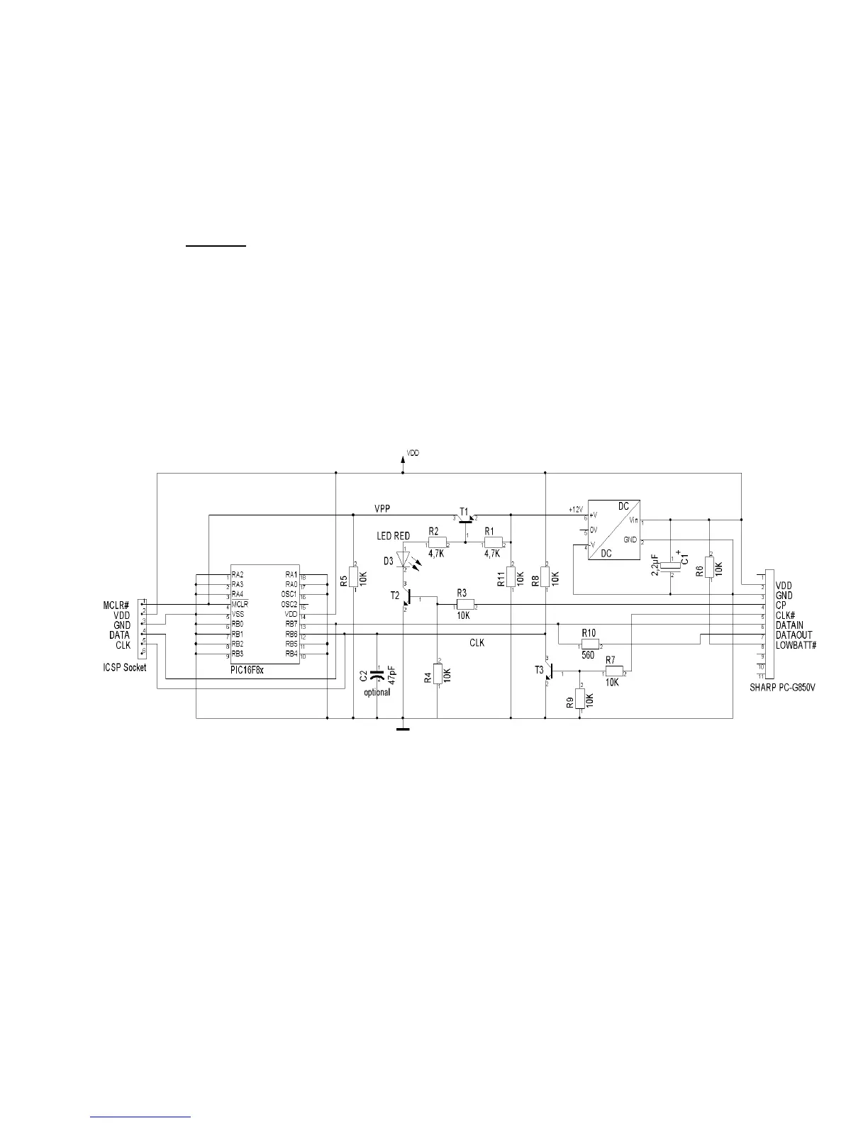
A +5V to +12V DC/DC-converter like the TMA0512C (or ~D) can be used to provide the burning voltage.
The CP-signal controls this as VPP for the MCLR#-pin through the transistors T1 and T2. The LED serves
as an indicator for ICSP-mode. T3 and R8 are inverting the CLK#-signal which then is connected as CLK to
the PICs RB6. C2 (as a low-pass filter) works for interference elemination at the CLK-signal if necessary.
The low voltage indicator only raises an exception, if the operation voltage supply falls below the LOW-
threshold (i.e. logic 0) during the programming phase.