17
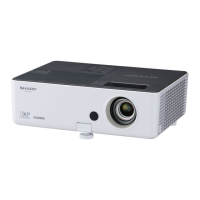
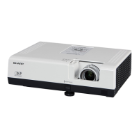
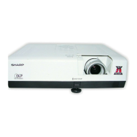
PG-A10S
PG-A10S-SL
AN-A10T
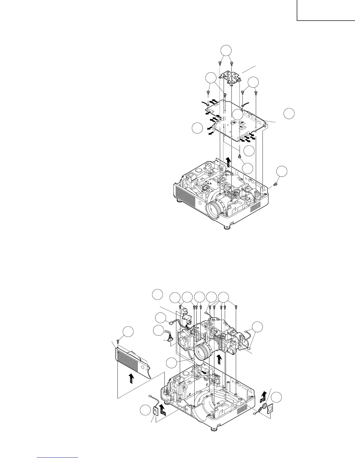
Operation Button
MAIN PWB
3-1
3-3
3-1
3-1
3-1
3-2
3-2
3-2
[FA]
[FC]
[EA]
[TF]
[FD]
[BP]
[GP]
[RP]
[FG]
[RC]
[LF]
[FE]
[TI]
[SP]
[FB]
[TH]
3-4
3. Removing the main PWB unit
3-1. Remove the seven screws.
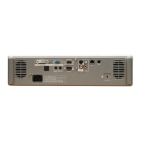
3-2. Remove all the connectors from main PWB.
3-3. Detach the main PWB.
3-4. Remove the two screws and detach the operation
button unit.
4.Removing the exhaust cover, optical mechanism unit, R/C receiver PWB
and speaker
4-1. Remove the two screws and detach the lamp socket.
4-2. Detach the Power/Ballast holder cover.
4-3. Remove all the connectors from optical mechanism unit.
4-4. Remove the nine screws and take out of the optical mechanism unit and the exhaust cover.
4-5. Detach the R/C receiver PWB.
4-6. Detach the Speaker.
Exhaust
Cover
Lamp
Socket
4-4
4-1
4-1
4-2
4-3
4-3
4-4
4-4
4-5
4-6
R/C Receiver PWB
Speaker
Optical mechanism unit
4-3
4-3
4-3
Power/Ballast
Holder Cover