I
.
Check that the copy lamp harness does not contact the mirror
base drivewire.
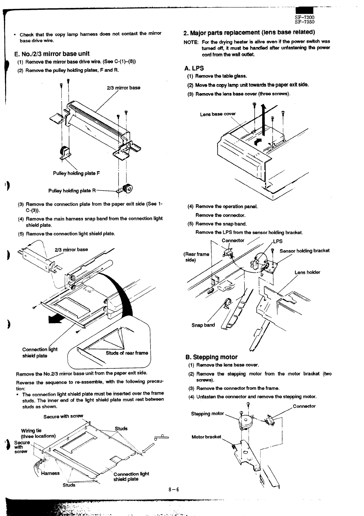
E. No./2/3 mirror base unit
(1) Removethe mirrorbaeedrive wire. (See C-(1~(8))
(2) Removethe pulleyho~ingpktee, F and R.
~ mirrorbase
/
.... ... ...
Pulky hti’ing phte F ‘
Pulby ho~ing plate R
+
(3) Remove the connectionplate from the paper exit side (See 1-
C-(3)).
(4)
Removethe mainharnesssnap bandfromthe connectionIght
shieMplate.
(5)Removethe connectionIght shieldplate.
1
\
L
/
Removethe No.Z3 mirrorbase unitfromthe paper exit side.
Reverse the quence to rsassembb, with the followingprecau-
tion:
● The connectionlightshieti plate must& insetied overthe frame
studs.The inner end of the Ight shi~ plate must restbetween
studsas shown.
securewithscrew
\
.
Wiringtie
‘e,,
studs
0’
(threelocations) “ ‘“~z
Secure
t~
/
with
../. ,/’
“<::,\ /+
screw
\
. ....
~ ~’” :,:,..
.,.,
P..\ “
Harness ~
.’
‘ connection I@ht
‘~
sh.wtiplate
Studs
8–6
SF-7300
SF-7350
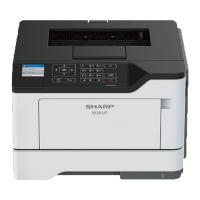
2. Majorpafis replacement(lens baserelatd)
NOTE: For the dryingheater b dive even if the power switchwas
turnedoff, it must be handti after unfasteningthe power
cod fromthe wall outfet.
A. LPS
(1)
Removethetebkghss.
(2) Move the copylamp unittowardethe p- exk side.
(3) Removethe Iensbeee cover (threescrews).
7 \
Lens base COVW
(4) Removethe operationpanel.
Removethe contior.
(5) Removethe snapband.
Removethe LPS fromthe sensorhoHingbracket.
Y
(1
B. Steppingmotor
(1)Removethe kns base cover.
(2) Remove the stepping motor from the motor bradet (two
screws).
(3) Removethe corm-orfrom the frame.
(4) Unfastenthe connectorand removethe steppingmotor.
?
,Connector
Motorbracket
%
J
\)oG, ~-
“ \ \
\
k\\
.,——-.