32
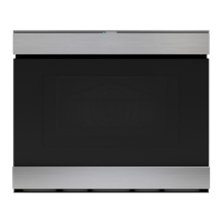
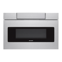
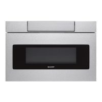
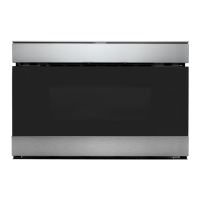
SMD2499FS
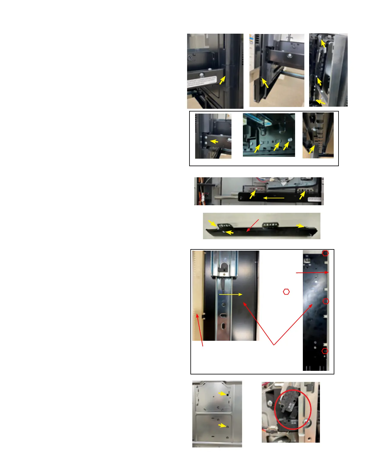
DRAWER/SLIDE RAIL/CHOKE/DOOR FRAME & RACK GEAR REMOVAL
DOOR FRAME ASSY REMOVAL
Fig. D-1 Fig. D-2
Fig. D-3
Support Angle Bottom
Rack Gear
1. Open the drawer and keep it open.
2. Remove (2) Drawer Support Covers (both sides) from Choke
Cover as shown in (Fig. D-1).
3. Carefully unsnap choke from Door Frame using a Putty Knife
and/or similar tool. (Fig. D-2)
4. Remove (9) screws from holding the Door panel to the Door
Frame. (Fig. D-3)
5. Release the tabs holding the Door Frame Assy to the Door
panel assy. (Fig. D-3)
DOOR CHOKE AND PANEL REMOVAL
1. Follow "Door Frame Assy Removal".
2. Remove the screws from the left (2), right (2) & bottom Slide
Rails (2). (Fig. D-4)
3. Unhook tabs holding the Slide Rails to the Door Panel Assy.
(Fig. D-4)
4. You can now remove and replace the Choke and/or Door
Panel Assy.
SLIDE RAILS, SUPPORT ANGLE & RACK
GEAR REMOVAL
1. Remove either the right or left O/C.
2. Follow Door Frame and Panel removal.
3. For the right or left Slide Rails remove (2) screws from Slide
Rail holder. (
Fig. D-5)
4. Pull the Slide Rail back towards the rear to release through
Faceplate slots.
Fig. D-5)
5. To replace the Support Angles or Slide Rail, remove (2) screws
and unclip Slide Rail to release. (
Fig. D-6)
6. To replace Rack Gear, pull bottom Slide Rail out and release
by moving the black lever to the right to release. Turn upside
down and remove (3) screws.
Fig. D-7
7. For the "BOTTOM SLIDE RAIL/SUPPORT ANGLE" removal,
turn oven on its back to access screw holes in bottom cover.
Push hole cover in and remove (2) screws holding the Slide
Rail to cavity.
Fig. D-8
8. Pull Slide Rail/Support Angel out.
9. Proceed in reverse order to reinstall.
To reassemble, just reverse the above order.
After reassembly, do the following.
(A) Make sure that door sensing switch, primary interlock
switch and monitor switch are operating properly. (
Fig.
D-9)
(B) An approved microwave survey meter should be used
to assure compliance with proper microwave radiation
emission limitation standards.
After any servicing, make sure of the following :
1. Drawer latch heads smoothly catch latch hook through latch
holes and that latch head goes through center of latch hole .
2. Deviation of door alignment from horizontal line of cavity face
plate is to be less than 1.0mm.
3. Drawer is positioned with its face pressed toward cavity face
plate.
4.
Reassemble the unit and check for microwave leakage around
drawer with an approved microwave survey meter. (Refer to
Microwave Measurement Procedure.)
Fig. D-7
Rack Gear
Screws
Fig. D-4
Fig. D-5
Fig. D-6
Fig. D-8
Fig. D-9
Support Angle