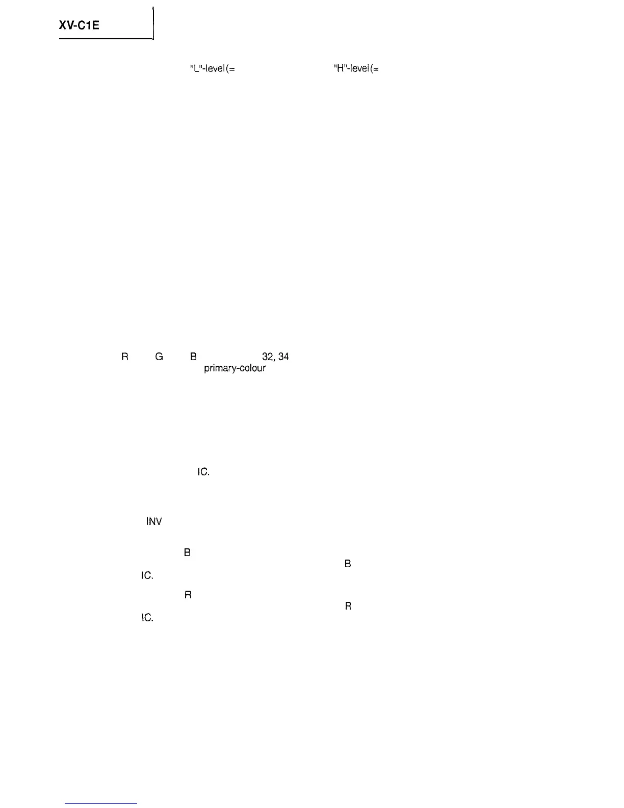
XV-CIE
1
l
SYNC IN (pin No. 21)
Used to receive
“L”-level
(=
OV) pulse for sync and
“H”-level
(=
3V) pulse otherwise. The sync signal received
and the sync signal separated by the sync separation circuit are fed through an OR gate and then into the
gate pulse generator circuit.
l
TIME CONSTANT (pin No. 22)
Used to make gate pulse width setting according to CR time constant.
l
PICTURE (pin No. 23)
Used to receive DC voltage for adjusting the video system’s frequency characteristic.
l
KILLER FILTER (pin No. 24)
Used to connect a filter for killer detection.
l
TINT (pin No. 25)
Used to receive DC voltage to adjust the tint.
l
VCO OUT (pin No. 26)
Used to output the oscillator circuit signal.
l
APC FILTER (pin No. 27)
Used to connect an APC detection filter.
l
VCO IN (pin No. 28)
Used to receive the oscillator circuit signal.
. GND (pin No. 29)
Grounding terminal.
l
R
OUT,
G
OUT,
B
OUT (pin Nos.
32,34
and 36)
Used to output the primary-colour signals that are inverted according to the inversion signal.
l
VCC2 (pin No. 33)
Used to connect the positive-polarity power for RGB output.
. OUT DC DET (pin No. 35)
Used to connect a capacitor to detect the output DC bias.
l
RGB AMPLITUDE (pin No. 38)
Used to adjust the amplitude between the inverted RGB output and the non-inverted one. This terminal is
preset inside the
IC.
l
FRP (pin No. 39)
Used to receive the inverted signal.
l
RGB
INV
(pin No. 40)
Used to receive voltage to switch the RGB output polarity according to the FRP polarity.
l
SUB BRIGHT
B
(pin No. 41)
Used to receive DC voltage for fine adjustment of the
B
signal’s luminance level. This terminal is preset inside
the
IC.
l
SUB BRIGHT
R
(pin No. 42)
Used to receive DC voltage for fine adjustment of the
R
signal’s luminance level. This terminal is preset inside
the
IC.
26