3
MFP023-E52-B
Mar. 2006
Contents may be changed for improvements without notice.
Copyright© SHIMADEN CO., LTD. All rights reserved.
FP23 2-input
Quick Reference
http://www.shimaden.co.jp/
For questions, please contact
YOUR LOCAL AGENT or
exp-dept@shimaden.co.jp
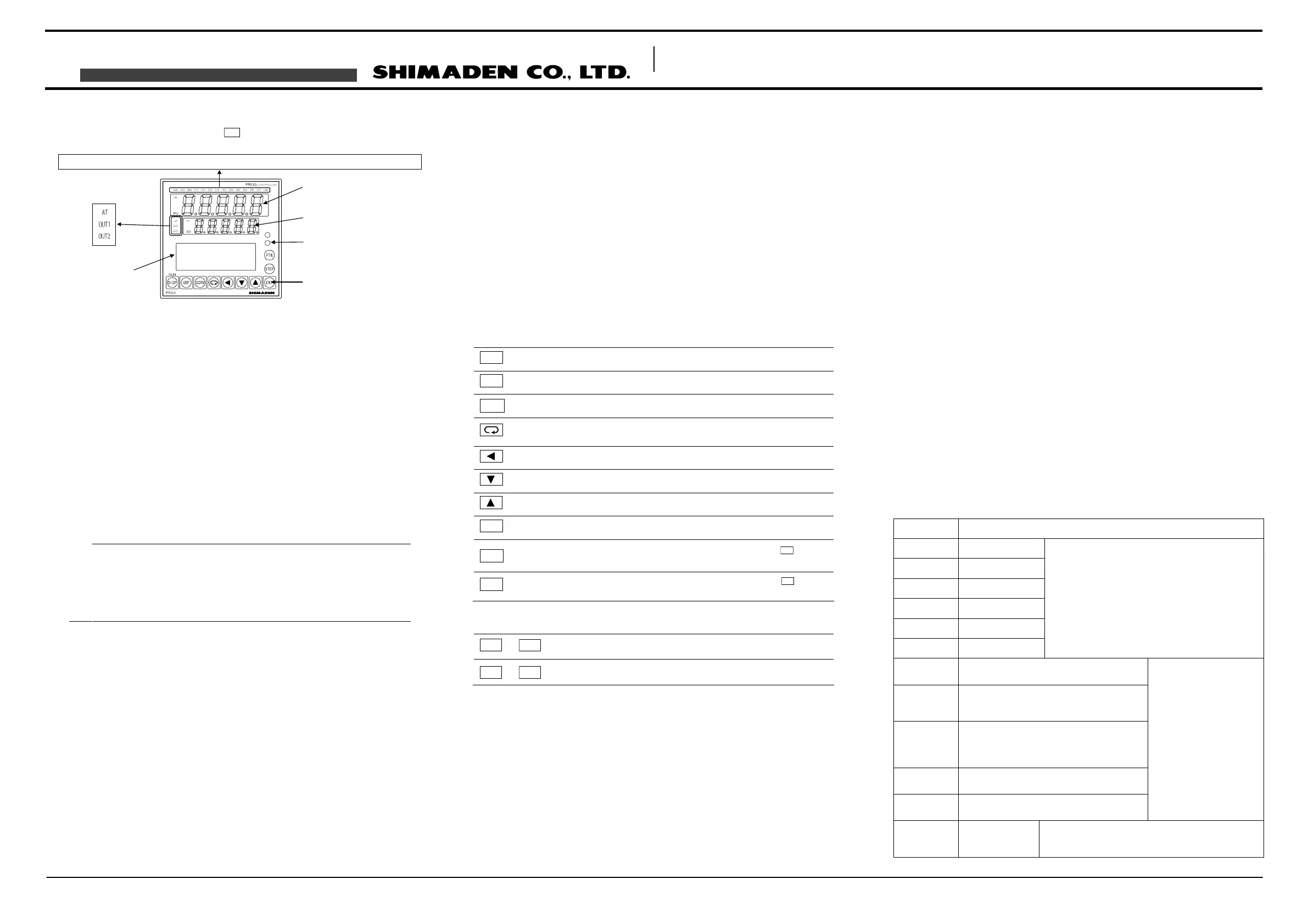
Names and Functions of Parts on Front Panel
If the instrument is 2-loop specification, it has three kinds of display mode. The display mode
can be switched to another by pressing
DISP
key on the front panel.
1PV display
For 2-loop;
Display mode 1: Displays the current measured value (PV) or an error message of CH1.
Display mode 2: Displays the current measured value (PV) or an error message of CH2.
Display mode 3: Displays the current measured value (PV) or an error message of CH1.
For other than 2-loop;
Displays the measured value (PV) or an error message.
2SV display
For 2-loop;
Display mode 1: Displays the target set value (SV) of CH1.
Display mode 2: Displays the target set value (SV) of CH2.
Display mode 3: Displays the current measured value (PV) of CH2.
For other than 2-loop;
Displays the target set value (SV).
Note
When it is under Display mode 1, CH1 PV value is shown on the PV display,
and CH1 SV value is shown on the SV display.
When it is under Display mode 2 (when CH2 lamp lights), CH2 PV value is
shown on the PV display, and CH2 SV value is shown on the SV display.
When it is under Display mode 3 (when PV lamp lights), CH1 PV value is
shown on the PV display, and CH2 PV value is shown on the SV display.
3LCD display (21 characters x 4 lines, max.)
For 2-loop, the following “CH1” information is displayed under Display mode 1 or 3, and the
following “CH2” information is displayed under Display mode 2.
Pattern/step No. display
Displays the pattern/step No. in the Program mode.
In the FIX mode, "F" is displayed at the PTN field and "- - -" is displayed at the STEP field.
"- - - " at the STEP field goes out during control execution (RUN) in the FIX mode.
Output (OUT) display
The control output value is displayed by a numerical value and a bar graph as a
percentage (%).
Channel (CH1 or CH2)
Displays the current channel for the data as one of the parameter values (2-loop
specification only).
IN1/IN2 PV
Displays the PV values of INPUT1/INPUT2 (2-input specification only).
CH1/CH2 actions
Displays the actions of the channel that is not displayed on LED indicators. (2-loop
specification only).
Program monitor display
Displays the program status monitor.
Remaining step time display
Displays the remaining step time during program operation.
Pattern graph display
Displays the pattern (step) graph during program operation.
Screen title display
Displays the screen group title in the respective screen group top screen.
Setup parameter display
Parameters can be selected and displayed by front key operation.
4Front panel key switches
The following key combination operations are available in screens from 0-1 to 0-7.
5LED indicators
Note that for 2-loop specification, each RUN, HLD, MAN, FIX, EXT, AT lamp shows different
channel information depending on the Display mode.
For 2-loop;
Display mode 1: Displays the action status of CH1.
Display mode 2: Displays the action status of CH2.
Display mode 3: Displays the action status of CH1.
For other than 2-loop;
Displays the action status.
Status lamps
RUN green Lights during program execution.
HLD green Lights when the program is paused. Blinks when the pause has
caused by an input error.
MAN green Blinks when control output is set to manual operation (MAN).
FIX green Lights in the FIX mode.
EV1 orange Lights during EV1 action.
EV2 orange Lights during EV2 action.
EV3 orange Lights during EV3 action.
DO1 orange Lights during DO1 action.
DO2 orange Lights during DO2 action.
DO3 orange Lights during DO3 action.
DO4 orange Lights during DO4 action.
DO5 orange Lights during DO5 action.
EXT green Lights when start pattern No. selection (PTN2bit, PTN3bit, PTN4bit,
PTN5bit) are set to DI5 to DI8.
COM green Lights during communication (COM) mode.
AT green Blinks during execution of auto tuning, and lights during standby.
OUT1 green When control output is current or voltage output, the brightness of
this lamp changes according to fluctuation of Control Output 1, and
during contact or SSR drive voltage output, this lamp lights when
Control Output 1 is ON and goes Out when Control Output 1 is OFF.
OUT2 green When control output is current or voltage output, the brightness of
this lamp changes according to fluctuation of Control Output 2, and
during contact or SSR drive voltage output, this lamp lights when
Control Output 2 is ON and goes Out when Control Output 2 is OFF.
Monitor lamps (2-input specification only)
CH2 green Lights when CH2 PV/SV values are displayed on PV/SV display
respectively.
PV green Lights when CH2 PV value is displayed on SV display.
Error Messages
Code Cause
ROM error
RAM error
EEPROM error
Input 1 A/D error
Input 2 A/D error
Hardware error
The error codes on the left are displayed on the PV
display.
These indicate that all outputs turn OFF or become 0%.
If any of the messages are displayed, repair or
replacement is required. Immediately turn the power
OFF, and contact your dealer.
The PV value exceeded the measuring range
lower limit (-10%FS).
The PV value exceeded the measuring range
higher limit (+110%FS), RTD-A burnout, or
thermocouple burnout.
One or two RTD-B burnout, or all leads of the
RTDs burnout.
Action of this device in this case is PV moving
excessively towards the higher limit.
Reference junction compensation (-20°C) is at
the lower limit. (thermocouple input)
Reference junction compensation (+80°C) is at
the higher limit. (thermocouple input)
When a PV input-related
abnormality is detected
during execution of control
on this device, the error
codes on the left are
displayed on the PV display.
Check input or the heater
lead. If the input or the
heater lead is not in error
and there is another
probable cause, contact
your dealer.
HB_HH
The heater current
exceeds 55.0A.
When a heater current abnormality is detected during
execution of control on this device this error code is
displayed on the LCD.
DISP
Displays the basic screen. Switches the Display mode.
GRP
Changes the screen group. Or, returns to the screen group top screen.
SCRN
Switches the parameter display screen in a screen group.
Selects the parameter to set up or change. The parameter to be changed is
indicated by the cursor (►).
Moves the digit in set numerical values.
Decrements parameters and numerical values during setup.
Increments parameters and numerical values during setup.
ENT
Registers data or parameter numerical values.
STEP
At a reset, increments the start step No. in the basic screen. (
ENT
must be
pressed to register.)
PTN
At a reset, increments the start pattern No. in the basic screen. (
ENT
must be
pressed to register.)
ENT
+
PTN
Hold (HLD) operation
ENT
+
STEP
Advance (ADV) operation
Infrared
LED indicators
LCD display
PV display
SV display
Interface
Front panel
key switches
RUN
HLD
MAN
FIX
EV1
EV2
EV3
D01
D02
D03
D04
D05
EXT COM
 Loading...