‐8‐
.9.
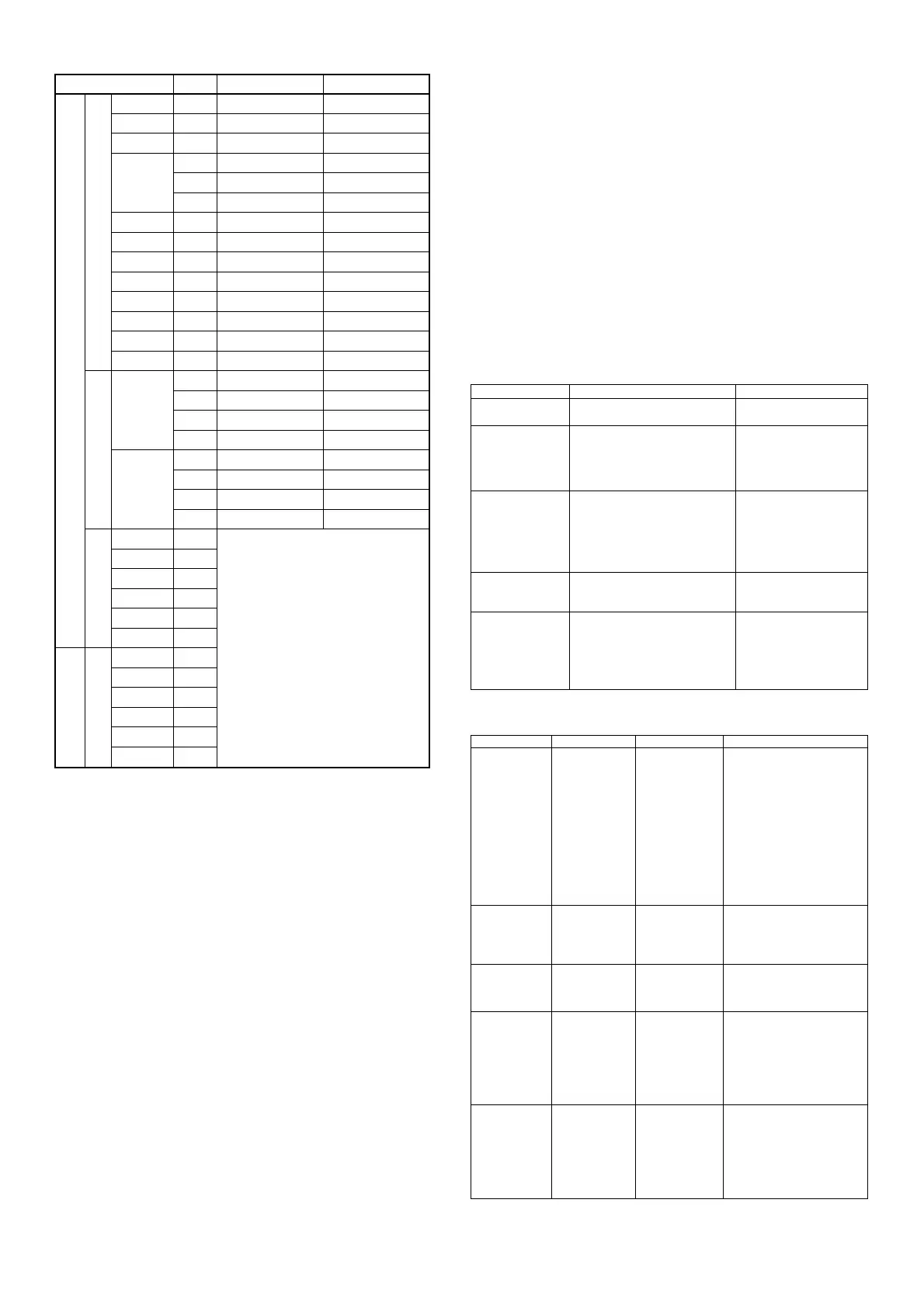
Table of Measuring Range Codes
Input type
Code
Measuring range
(°C)
Measuring range
(°F)
Multi
Thermocouple
B
*1
01
0.0 - 1800.0
0.0 - 3300.0
R
02
0.0 - 1700.0
0.0 - 3100.0
S
03
0.0 - 1700.0
0.0 - 3100.0
K
04
−199.9 - 400.0
−300.0 - 750.0
05
0.0 - 800.0
0.0 - 1500.0
06
0.0 - 1200.0
0.0 - 2200.0
E
07
0.0 - 700.0
0.0 - 1300.0
J
08
0.0 - 600.0
0.0 - 1100.0
T
09 *2
−199.9 - 200.0
−300.0 - 400.0
N
10
0.0 - 1300.0
0.0 - 2300.0
PLII
*3
11
0.0 - 1300.0
0.0 - 2300.0
WRe5-26
*4
12
0.0 - 2300.0
0.0 - 4200.0
U
*5
13 *2
−199.9 - 200.0
−300.0 - 400.0
L
*5
14
0.0 - 600.0
0.0 - 1100.0
R.T.D.
Pt100
31
−200.0 - 600.0
−300.0 - 1100.0
32
−100.0 - 100.0
−150.0 - 200.0
33
−50.0 - 50.0
−50.0 - 120.0
34
0.0 - 200.0
0.0 - 400.0
JPt100
35
−200.0 - 500.0
−300.0 - 1000.0
36
−100.0 - 100.0
−150.0 - 200.0
37
−50.0 - 50.0
−50.0 - 120.0
38
0.0 - 200.0
0.0 - 400.0
mV
−10 - 10
71
Initial value: 0.0 - 100.0
Span: 10 - 5000 digit
Position of decimal point: None
1, 2 or 3 digits on the right of decimal point
Lower limit value < Higher limit value
0 - 10
72
0 - 20
73
0 - 50
74
10 - 50
75
0 -100
76
Voltage
V
−1 - 1
81
0 - 1
82
0 - 2
83
0 - 5
84
1 - 5
85
1 - 10
86
Thermocouple B, R, S, K, E, J, T, N: JIS/IEC
R.T.D. Pt100: JIS/IEC JPt100/Former JIS
*1 Thermocouple B: Accuracy guarantee not applicable to
400˚C (752˚F) and below.
*2 Thermocouple Thermocouple is K, T, U and indicates ±
(0.5%FS+1 digit) when accuracy is 0
-
100˚C and ± (1.0%FS+1 digit) when
accuracy is below 100˚C.
*3 Thermo
couple
PLII Platinel
*4 Thermo
couple
WRe5-26 (ASTM988)
*5 Thermo
couple
U, L (DIN 43710)
Note: Unless otherwise specified, the measuring ranges are K thermocouple
0.0-800.0˚C for multi input and 0-10VDC: 0.0 - 100.0 for voltage (V)
input at the time of shipment from the factory.
Note: Do not use the above sensors (current/voltage, thermocouple, R.T.D.)
for the measurement of power supply line.
10. Maintenance and Troubleshooting
10-1. Procedure of Maintenance Replacement and Matters
Be attended to (Steps for replacing defective items)
Confirmation of Model Code:
Check the model code of the component part in trouble.
(Open the control box, and you can find an appropriate code in the
model label affixed to the instrument case.)
Inquiry on Input Data:
Ask the manufacturer if input data (control date of external
operation, event output, set value of position, etc. at the time when
an error occurs) is necessary or not.
Confirmation of Present Wiring Condition:
Check and record the present wiring condition. Please note that in
case input data is necessary for control, the same control operation
as before is not possible with a replaced product unless such data
is input.
Confirmation of Present Input Data:
When data is not known, call the input date for the product, check
and record it. In case input data is required, the same control
operation as before is not with a replaced product unless such data
is input.
Repair of Present Product or Procurement of New Product:
In case the product in trouble is removable from the site of
installation, remove and have it repaired. If it is not possible,
arrange to acquire a new product for replacement.
Setting before Starting Operation:
When replaced by a new product, check the wiring, apply power
and set items as described in 8. Before Starting Up.
10-2. Cause of Trouble and Troubleshooting
Problem Cause Remedy
Error code is
displayed.
Refer to "Error Codes, Causes
and Remedies."
Refer to "Error Codes,
Causes and Remedies."
Displayed PV
value seems
to be incorrect.
Set measuring range code is
different from that of input
sensor/input signal.
Erroneous wiring to input
terminals of sensor
Check if set measuring
range code is correct
for input signal.
Correct wiring to input
terminals of sensor.
Display on the
front panel
goes out and
the instrument
does not
operate.
Problem with power supply
and wiring
Deterioration of the
connection product.
Inspect portions related
to power source and
wire connection.
Check wiring.
Examine the product
and repair or replace.
Key unable to
be operated.
Keylock is in effect.
Deterioration of the product.
Release keylock.
Examine and repair or
replace the product.
ON-OFF action
of control
output is too
fast.
ON-OFF is set for P of PID.
Too small a value set for
hysteresis of ON-OFF action.
Change the OFF set for
P to two-position type
ON-OFF action.
Increase the hysteresis
value of ON-OFF
action.
10-3. Error Codes, Causes and Remedies
(Inputmeasuredvalueproblems)
Screen display Problem Cause Remedy
(HHHH)
Higher limit side
scale over
A break of
thermocouple
input wiring
A break of
R.T.D. input
wiring
Input
measured
value
exceeded
measuring
range higher
limit of by 10%.
Check thermocouple input
wiring for a possible break.
Check R.T.D. input A wiring
for a possible break. If
wiring has no problem,
replace R.T.D.
For voltage or current input,
check the transmitting unit
of measured values.
Check if set code of
measuring range is correct for
input signal.
(LLLL)
Lower limit side
scale over
Input measured
value fell from
lower limit of
measuring range
by 10%.
Check wiring of inversed
polarity for measured value
input.
(b----)
A break of
R.T.D. input
wiring.
A break of B
Breaks of ABB
Check R.T.D. input terminals
A, B and B for breaks. If
wiring has no problem,
replace R.T.D.
(CJHH)
Higher limit side
scale over of
cold junction
(CJ) of
thermocouple
input.
Ambient
temperature of the
product has
exceeded 80°C.
Reduce ambient
temperature to the level
provided in the environment
conditions for the product.
In case ambient
temperature has not
exceeded 80°C, examine
the product.
(CJLL)
Lower limit side
scaleover of cold
junction (CJ) of
thermocouple
input.
Ambient
temperature of the
product has fallen
to 20°C or lower.
Raise ambient temperature
to the level provided in the
environment conditions for
the product.
In case ambient
temperature has not fallen
to 20°C, examine the
product.

 Loading...