4-7.Terminal Arrangement Table
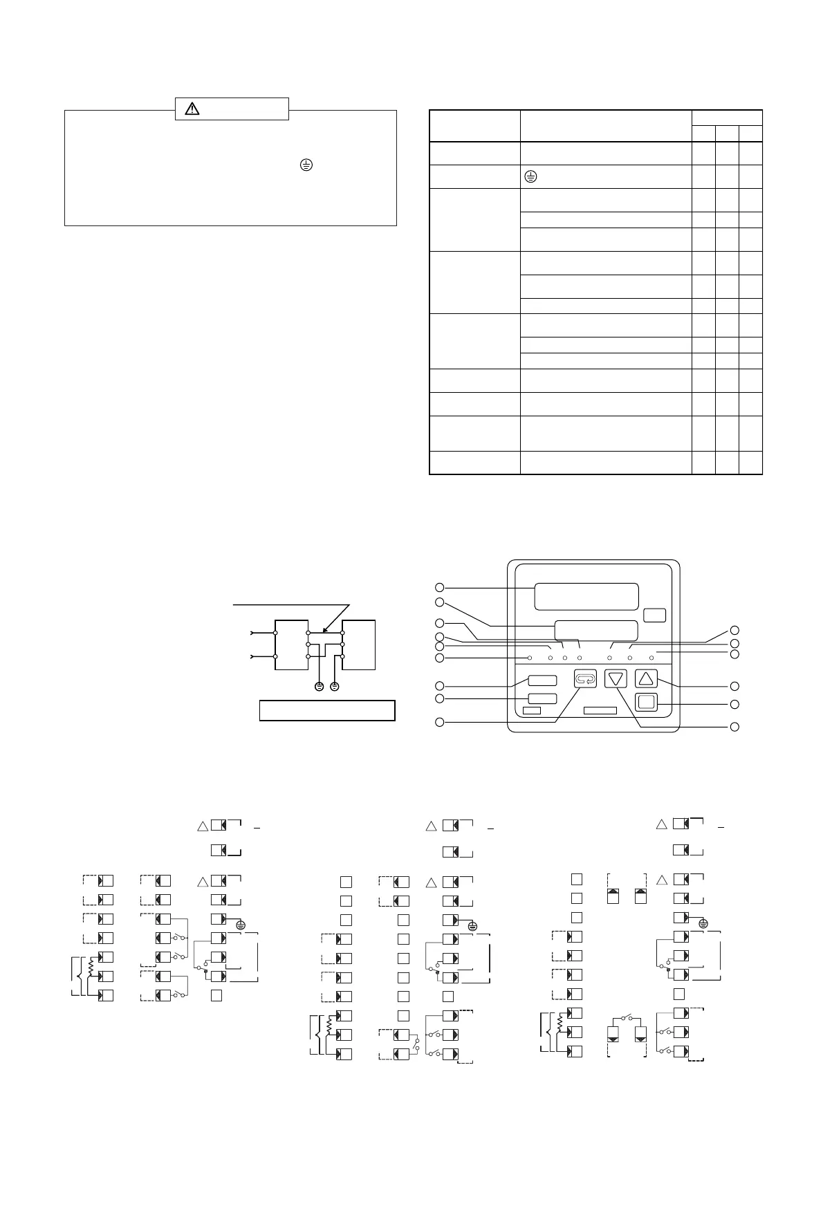
5. Names and Functions of Parts
- 6 -
4-5.Wiring
(1) Follow the terminal layout shown in section 4-6 and make sure to
carry out the correct wiring.
(2) Press-fit terminal must fit an M3.5 screw and have a width of 7 mm
or smaller.
(3) In the case of the thermocouple input, use a compensating conductor
compatible with the type of thermocouple selected.
(4) In the case of R.T.D. input, the resistance of a single lead wire must
be 5Ω or less and the three wires must have the same resistance
value.
(5) The input signal wire must not be accommodated with a high-
voltage power cable in the same wiring conduit or duct.
(6) Shielded wire (one-point grounding) is effective to avoid
electrostatic induction noise.
(7) An effective way to avoid magnetic induction noise is to twist the
input wires at short and equal intervals.
(8) The wiring for power supply must be a 600V vinyl insulated wire or
cable having a cross-section area of 1 mm
2
or larger or a wire or
cable of the same or better performance.
(9) The wire for grounding must be larger than 2 mm
2
and must be
grounded at a grounding resistance of 100Ω or lower.
(10) Noise filter
If the instrument appears to
have noise interference caused
by the power supply, use a
noise filter to prevent erroneous
functioning.
Install a noise filter on the
grounded panel and make the
wire connecting the noise filter
OUT terminal and the power
supply terminal on the controller as short as possible.
4-6.Terminal Layout
Name of terminal
Description
Terminal No.
Power supply
terminal
100-240V AC, 24V DC, or 24V AC
Protective conductor
terminal
Input terminal
Control output
terminal
Alarm output
terminal
Heater break alarm
CT input terminal
Set value bias
input terminal
Event/heater break
alarm output
terminal
Analog output
terminal
R.T.D.: A,
Thermocouple, voltage, current: +
R.T.D.: B
R.T.D.: B,
Thermocouple, voltage, current: -
Contact: COM,
SSR drive voltage, voltage, current: +
Contact: NO,
SSR drive voltage, voltage, current: -
Contact: NC
Contact: COM
Contact: AL (lower limit)
Contact: AH (higher limit)
Contact: NO
Voltage or current
SR62 SR63 SR64
8-9 11-12 11-12
10 13 13
588
699
71010
11 14 14
12 15 15
13 16 16
17 18 18
18 19 19
19 20 20
3-4 6-7 6-7
1-2 4-5 4-5
20-21 29-30 23-24
15-16 21-22 21-22
DISP
AT
PV
SV
ENT
OUT AH AT MAN SBAL EV/HB
1
7
13
14
15
10
11
12
8
9
2
3
4
5
6
Noise filter
IN OUT
100—
240V
~
AC
~
100—
240V AC
50/60Hz
Grounding Grounding
Recommended noise filter:
ZMB2203-13 manufactured by TDK
Make this wire as short as possible.
Controller
• When wiring, make sure to disconnect the power supply.
Otherwise an electric shock may result.
• Make sure the protective conductor terminal ( ) is grounded.
Otherwise an electric shock may result.
• Do not touch terminals or other charged elements with power
supplied after wiring.
WARNING
100-240VAC
/24VAC ~
24VDC... 6W
B
--
A-output
1.5A240VAC
AH
1.5A240VAC
AL
COM
1.5A240VAC
EV/HB
+
+
-
-
50/60Hz8VA
2.5A240VAC
0-20mA DC
OUTPUT
4-20mA DC
20mA15V DC
0-10V DC
0-5V DC
1
2
3
4
5
6
7
8
9
50/60Hz8VA
8
9
10
11
12
13
14
15
16
17
18
19
20
21
DC
SB
GR
A
++
B
CT
+
-
COM
NO
NC
SR62
!
!
!
SB
GR
A-output
1.5A240VAC
AH
1.5A240VAC
AL
COM
1.5A240VAC
EV/HB
+
+
-
-
100-240VAC
50/60Hz10VA
2.5A240VAC
0-20mA DC
OUTPUT
4-20mA DC
20mA15V DC
0-10V DC
0-5V DC
CT
1
2
3
4
5
6
7
8
9
10
+
-
DC
-
+
B
A
21
22
23
24
25
29
28
27
26
30
13
12
11
14
!
12
11
15
16
17
18
19
20
NC
-
+
NO
COM
/24VAC ~
24VDC... 6W
50/60Hz8VA
SR63
!
SB
GR
A-output
1.5A240VAC
AH
1.5A240VAC
1.5A240VAC
AL
COM
EV/HB
+
-
50/60Hz8VA
100-240VA
2.5A240VAC
0-20mA DC
OUTPUT
4-20mA DC
20mA15V DC
0-10V DC
0-5V DC
CT
+
-
DC
-
+
B
B
A
21
22
23 24
13
12
11
14
15
16
17
18
19
20
NC
-
+
NO
COM
1
2
3
4
5
6
7
8
9
10
+
-
!
12
11
/24VAC ~
24VDC... 6W
50/60Hz8VA
SR64