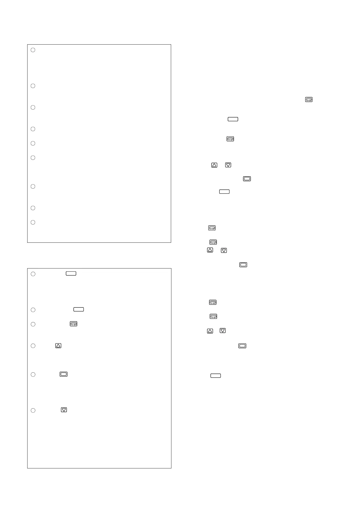
Display Section
Setting Section
- 7 -
6. Parameter Operating Procedure, Flow, and
Functions
6-1.Operating Procedure
(Parameter Flow and Functions are shown in section 6-2.)
(1) Turn on the power supply to display the "Mode 0-0" basic screen.
(2) The "Mode 0-0" basic screen displays the process value (PV) and the
set value (SV) which are the starting points of the respective
parameters.
(3) In order to move to the "Mode 1" screen group, press the key for
3 seconds or longer on the "Mode 0-0" basic screen.
(4) In order to move to the "Mode 2" function selection mode screen
group, press the key for 5 seconds or longer on the "Mode 0-
0" basic screen.
(5) In order to move from one screen to another within each screen
group, press the (parameter) key.
(6) If you select a desired screen No. to be called within the "Mode 1"
group on the first screen (Mode 1-0) in the "Mode 1" screen group,
you can move directly to that screen (direct call).
(7) Use the & keys to set the value on each screen (the decimal
point in the lowest place keeps flashing during the value setting
procedure) and press the key to register the value.
(8) The "Mode 0-0" basic screen can be accessed from any screen by
pressing the key.
"Mode 0" Operation Parameter Screen Group (Setting of the set
value, alarm/event action point, Sb, P, I, D)
• This screen group is subject to the most frequent setting modification.
• Press the key to move to "Mode 0-1" from the "Mode 0-0" basic
screen.
• Press the key to move to the next screen within the screen group.
• Use the & keys to set the value on each screen (the decimal
point in the lowest place keeps flashing during the value setting
procedure) and press the key to register the value.
"Mode 1" Operation Parameter Screen Group (Setting the value
for each function)
• This screen group is not often subject to frequent setting modification.
• Press the key for 3 seconds or longer to move to "Mode 1-0" from
the "Mode 0-0" basic screen.
• Press the (parameter) key to move from one screen to another
within the screen group.
• Use the & keys to set the value on each screen (the decimal
point in the lowest place keeps flashing during the value setting
procedure) and press the key to register the value.
"Mode 2" Function Selection Screen Group
• This group is used to select functions.
• Press the key for 5 seconds or longer to move to "Mode 2-1"
from the "Mode 0-0" basic screen.
•For the operating procedure on each screen, refer to section 7
"Operation" on page 19.
Display key
When this key is pressed in any of the parameter screens, the
display returns to the display / set value screen.
Pressing it for 5 seconds brings the initial value setting screen
(mode 2) on display.
Auto tuning key
This key is used to execute and stop auto tuning action.
Parameter key
This key is used to select a parameter to be set or changed. Press it
for 3 seconds to move to the parameter block in mode 1.
Up key
The flashing of the decimal point in the lowest place on the SV
display shows that the value is ready to be changed. Press this key
to increase a numeric data or to change selected character data.
Enter key
This key is used to register a changed data (the decimal point in the
lowest place flashes.) Once registered, the decimal point stops
flashing. If this key is pressed for 3 seconds on the output screen
(0-1), the mode changes to manual control.
Down key
The flashing of the decimal point on the lowest place on the SV
display shows that the value is ready to be changed. Press this key
to decrease a numeric data or to change selected character data.
DISP
AT
ENT
Process value (PV) display / red
Process values (PV) are displayed. When a parameter is set, its
type is displayed.
When something goes out of order in the system, an error message
is displayed.
Set set value (SV) display / green
Set set value are displayed. When a parameter is set, its value is
displayed.
Event / HB lamp (EV/HB) / red
The lamp lights when event output is on or heater break / heater
loop alarm output is on.
Lower limit alarm lamp (AL) / red
The lamp lights when lower limit alarm output is on.
Higher limit alarm lamp (AH) / red
The lamp lights when higher limit alarm output is on.
Output lamp (OUT) / green
The lamp lights when control output is on and its brightness
changes in proportion to the amount of output in the case of current
output and voltage output.
Auto tuning lamp (AT) / green
The lamp lights while auto tuning is in progress and remains lit
while standing by for AT action.
Manual control lamp (MAN) / red
The lamp flashes while in the manual control mode.
Set value bias lamp (SB) / green
The lamp lights while the set value bias action is in progress.