4(33)
6.1 Hopper Cleaning ................................................................................... 31
6.2 Main Body Cleaning .............................................................................. 32
6.3 Maintenance Schedule ......................................................................... 33
6.3.1 About the Machine ...................................................................... 33
6.3.2 Installation & Inspection .............................................................. 33
6.3.3 Daily Checking ............................................................................ 33
6.3.4 Weekly Checking ......................................................................... 33
6.3.5 Monthly Checking ........................................................................ 33
Table Index
Table 1-1: Specification ....................................................................................... 9
Picture Index
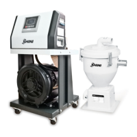
Picture 1-1:SAL-810G&SMH-6L .......................................................................... 5
Picture 1-2: External Dimension 1 ....................................................................... 8
Picture 1-3: Loading Capacity ........................................................................... 10
Picture 1-4: Material Suction Pipe Location Drawing ......................................... 11
Picture 2-1: Working Principle 1 ........................................................................ 12
Picture 2-2: Working Principle 2 ........................................................................ 13
Picture 2-3: Working Principle 3 ........................................................................ 14
Picture 3-1: Installation Layout 1 ....................................................................... 16
Picture 3-2: Installation Layout 2 ....................................................................... 17
Picture 3-3: Optional SCH-U Installation Layout ................................................ 18
Picture 3-4: Optional SPV-U Installation Layout ................................................ 19
Picture 3-5: Optional ACF-1 Installation Layout ................................................. 19
Picture 4-1: Panel .............................................................................................. 21
Picture 6-1: Hopper Cleaning ............................................................................ 31
Picture 6-2: Filter Barrel Cleaning Drawing ....................................................... 32