EasyManuals Logo

Shinkawa VM-5 User Manual

Default Icon
25 pages
To Next Page IconTo Next Page
To Previous Page IconTo Previous Page
Page #10 background imageLoading...
Page #10 background image
4. INTERCONNECTION VM-5G
-4-
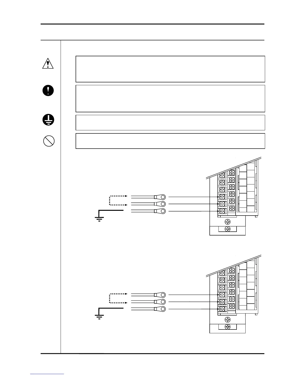
4-1 POWER SUPPLY WIRING
Beware of electric shock from high-voltage parts.
When using a DC power source, make especially sure not to reverse the polarities
as this will cause serious damage.
Make sure to confirm that the power supply voltage matches that of the equipment.
Use cables with AWG No.14 to No.18 gage (0.75 - 2mm
2
) stranded conductors for
wiring of the power supply input terminals.
Make sure to ground the GND terminal.
Caution
Mandatory
Prohibition
Connect earth
wire
VM-5G1,2 Single Unit Instrument Rack
Input / output terminal block
A13
NO
A14
NC
A15
OK
A16
NO
A17
+24V
A18
0V
A19
FG
B13
NO
B14
SEQ
B15
COM
B16
P-S
B17
RES
B18
COM
B19
FLT
F.G
0V
+24V or
+110V
Power supply input
(24VDC or 110VDC)
VM-5G0 Single Unit Instrument Rack
Input / output terminal block
A13
NO
A14
NC
A15
OK
A16
NO
A17
L1
A18
L2
A19
FG
B13
NO
B14
SEQ
B15
COM
B16
P-S
B17
RES
B18
COM
B19
FLT
F.G
L2
L1
Power supply input
(85 to 264VAC)

Questions and Answers:

Question and Answer IconNeed help?

Do you have a question about the Shinkawa VM-5 and is the answer not in the manual?

Shinkawa VM-5 Specifications

General IconGeneral
BrandShinkawa
ModelVM-5
CategoryAnalytical Instruments
LanguageEnglish

Related product manuals