4. INTERCONNECTION VM-5G
-6-
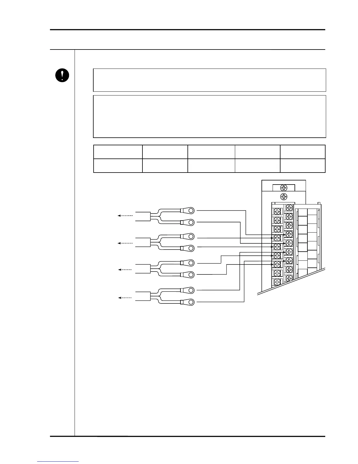
4-3 WIRING OF RECORDER AND BUFFER OUTPUT
• Make sure to insulate the buffer output against earth.
If not insulated, a 2-point earth system results, which may cause noise interference.
• In the case that VM-5G is used with VM-5C eccentricity monitor unit, the connection
wiring of the recorder output and buffer output shall be as the following table.
And in the case that VM-5G is used with the monitor unit with the one (1) recorder
output, the recorder output shall be output from the CH1 recorder output terminal.
Monitor unit
CH1
Recorder output
CH1
Buffer output
CH2
Recorder output
CH2
Buffer output
VM-5C
Eccentricity monitor
Eccentricity pk-pk
CH1 input
(Phase marker)
Direct
CH2 input
(Eccentricity)
Mandatory
A1
IN
A2
COM
A3
PWR
A4
REC+
A5
REC-
A6
BUF
A7
COM
A8
NC
B1
 Loading...