EasyManuals Logo

Shinkawa VM-5 User Manual

Default Icon
25 pages
To Next Page IconTo Next Page
To Previous Page IconTo Previous Page
Page #13 background imageLoading...
Page #13 background image
4. INTERCONNECTION VM-5G
-7-
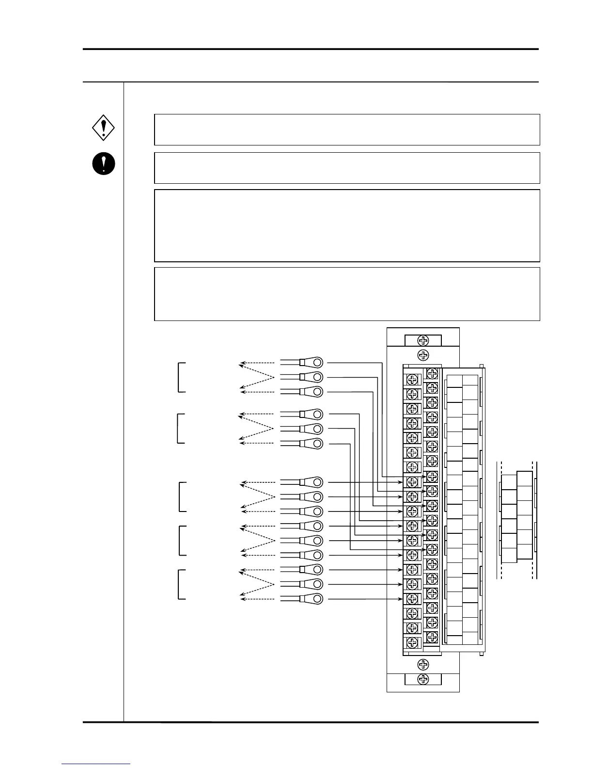
4-4 ALARM OUTPUT WIRING
Beware of electric shock from high-voltage parts.
Do not exceed the allowable contact capacity of the alarm contacts.
In the case that the alarm output type of the thrust monitor, the differential expansion
monitor etc. is CH1 : 4 points (H-DANGER, H-ALERT, L-ALERT, L-DANGER),
L-ALERT, L-DANGER shall be output respectively from CH2 ALERT, CH2
DANGER.
In the case that the alarm output type is voting logic such as AND or OR output of
CH1/CH2, CH1 ALERT terminal (SR1 for VM-5S, VM-5R) and CH1 DANGER
terminal (SR2 for VM-5S, VM-5R) shall be used for the connection.
Warning
Mandatory
A8
NC
A9
DAN
A10
NO
A11
NC
A12
ALE
A13
NO
A14
NC
A15
OK
A16
NO
A17
L1
A18
L2
A19
FG
B8
NC
B9
DAN
B10
NO
B11
NC
B12
ALE
B13
NO
B14
SEQ
B15
COM
B16
P-S
B17
RES
B18
COM
B19
FLT
A1
IN
A2
COM
A3
PWR
A4
REC+
A5
REC-
A6
BUF
A7
COM
B1
IN
B2
COM
B3
PWR
B4
REC+
B5
REC-
B6
BUF
B7
COM
A8
NC
A9
DAN
A10
NO
A11
NC
A12
ALE
A13
NO
B8
NC
B9
DAN
B10
NO
B11
NC
B12
ALE
B13
NO
CH2
DANGER
alarm output
OK
alarm output
NC contact
output
NO contact
out
p
ut
CH2
ALERT
alarm output
CH1
DANGER
alarm output
CH1
ALERT
alarm output
(VM-5S,R SR4)
(VM-5S,R SR3)
(VM-5S,R SR2)
(VM-5S,R SR1)
VM-5S
R
NC contact
output
NO contact
out
p
ut
NC contact
output
NO contact
out
p
ut
NC contact
output
NO contact
out
p
ut
NC contact
output
NO contact
out
p
ut
VM-5G Single Unit Instrument Rack
Input / output terminal block

Questions and Answers:

Question and Answer IconNeed help?

Do you have a question about the Shinkawa VM-5 and is the answer not in the manual?

Shinkawa VM-5 Specifications

General IconGeneral
BrandShinkawa
ModelVM-5
CategoryAnalytical Instruments
LanguageEnglish

Related product manuals