DMX Control
When dipswitch #10 is turned OFF all dimmers are controlled by a separate DMX channel. If dipswitch
#10 is turned ON all dimmers are controlled by a single DMX channel (parallel).
Example: normal mode
DMX CH 1: dimmer channel 1 DMX CH 4: dimmer channel 4
DMX CH 2: dimmer channel 2 DMX CH 5: dimmer channel 5
DMX CH 3: dimmer channel 3 DMX CH 6: dimmer channel 6
Example: parallel mode
DMX CH 1: dimmer channel 1 DMX CH 1: dimmer channel 4
DMX CH 1: dimmer channel 2 DMX CH 1: dimmer channel 5
DMX CH 1: dimmer channel 3 DMX CH 1: dimmer channel 6
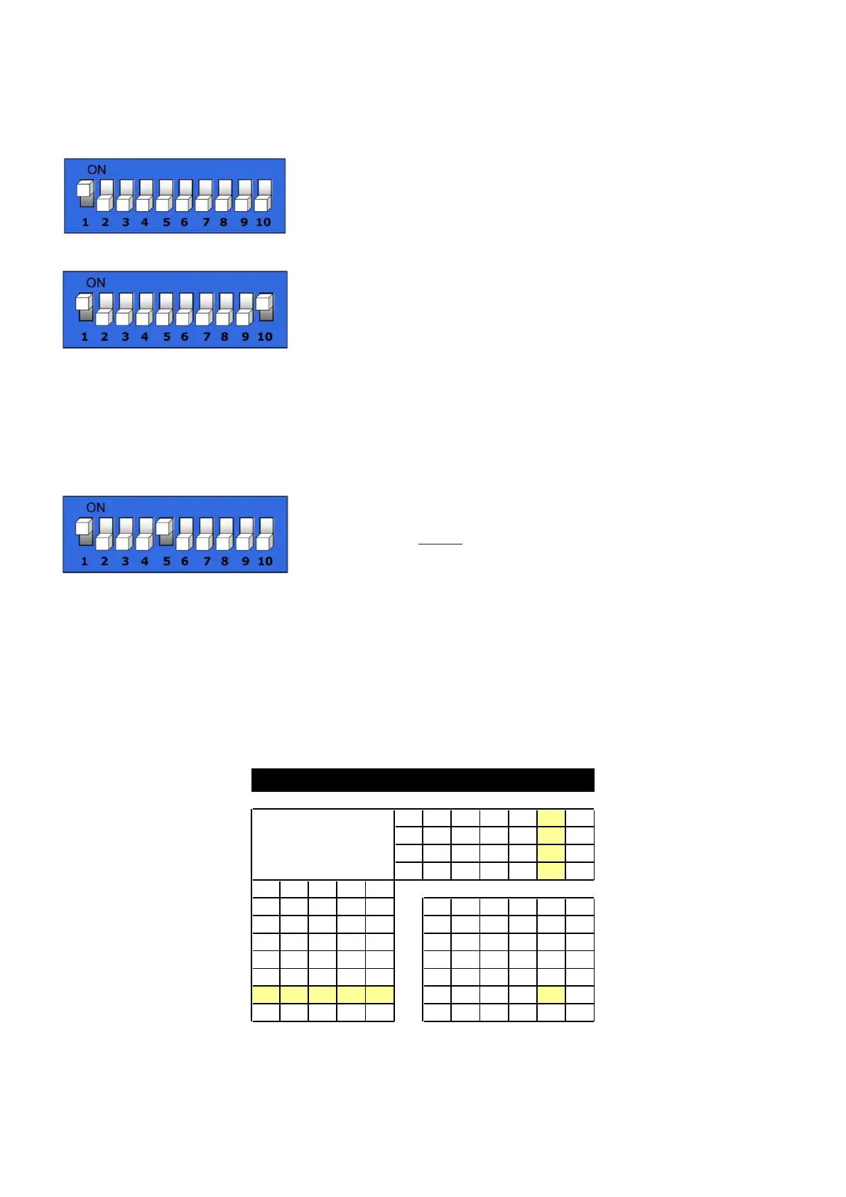
DMX Dipswitch Settings
DMX products must have their own "address" to receive DMX signals. Addresses on the controller are set
by flipping the appropriate DMX dipswitches.
You need to know that DMX address settings are the sum of the dip switch values where switch 1 = 2
0
,
switch 2 = 2
1
, switch 3 = 2
2,
, switch 4 = 2
3
etc., finally switch 9 = 2
8
.
Example
Switch Value
#1 (2
0
) 1
#5 (2
4
) 16 +
Total sum 17
A much better approach is using the DMX Address Quick reference Chart as shown in figure 5 on the
following page.
Example:
1. If you want to give an LED Wash Ultra DMX address133, you first have to find the number 133 in the
DMX Chart.
2. Then look at the left side (Dip Switches #1-#5) horizontally from 133.
In the Table you’ll see #1=ON, #2=OFF, #3=ON, #4=OFF, #5=OFF.
3. Finally look at the upper side of the table (Dip Switches #6-#9) vertically from 133.
In the Table you’ll see #6=OFF, #7=OFF, #8=ON, #9=OFF.
DMX Address Quick Reference Chart
0 0 0 0 0 32 64 96 128 160
1 0 0 0 0 1 33 65 97 129 161
0 1 0 0 0 2 34 66 98 130 162
1 1 0 0 0 3 35 67 99 131 163
0 0 1 0 0 4 36 68 100 132 164
1 0 1 0 0 5 37 69 101 133 165
0 1 1 0 0 6 38 70 102 134 166