7
System Overview
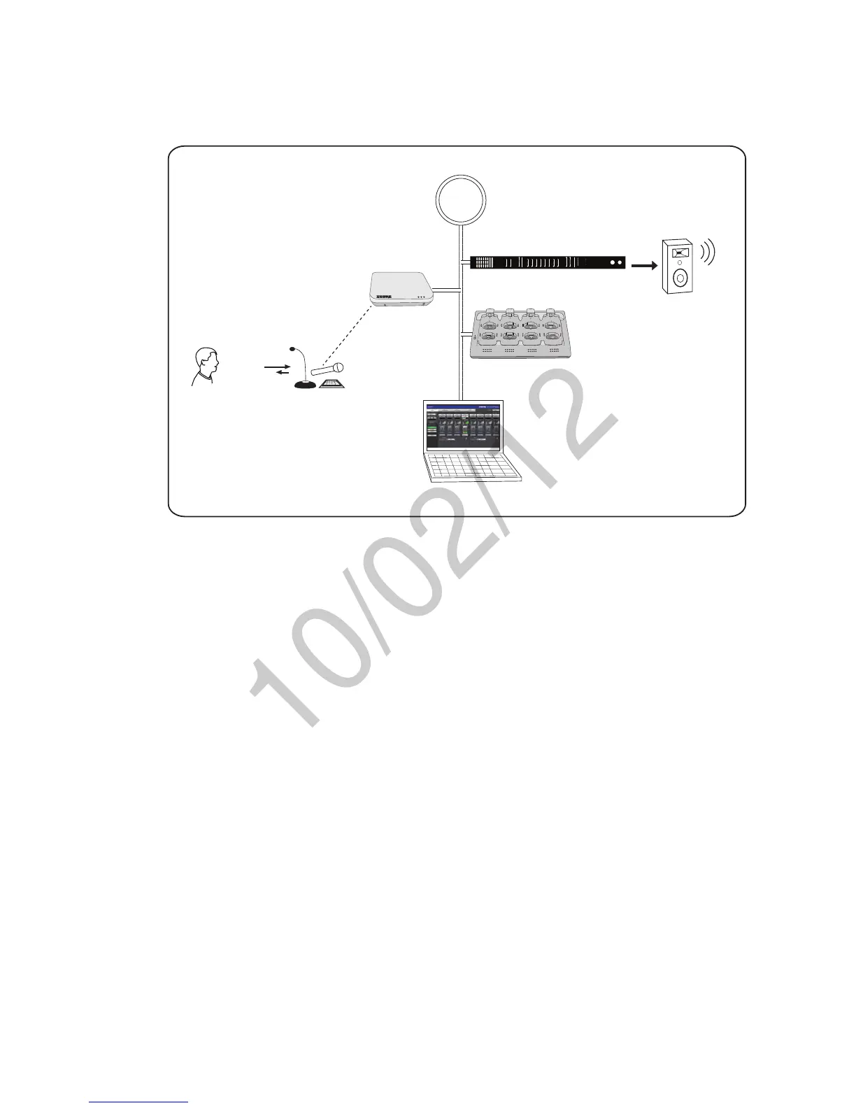
The following is an overview of each component and its function in the MXW system:
Network
INPUT: SPL
OUTPUT: Headphone
power
ethernet
network audio
lockout
-18
-24
0
-6
-12
line
aux
mic
mute
sig/clip
line
aux
mute
sig/clip
Audio Network Interface
HEADPHONE
-18
-24
-30
-36
-48
-60
-9
0
INPUT OUTPUT
push to solo | hold to mute adjust
A B 1 2 3 4 5 6 7 8
7
8
6
5
1
2
3
4
APT
NCS
GUI
ANI
①
②
③
④
⑤
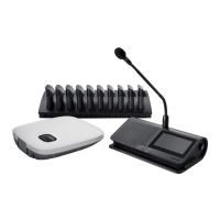
① MXW Microphones
•Convert audio into a digital RF signal that
transmits wirelessly to the APT.
•Available in a variety of form factors to
accommodate any event.
•Boundary and gooseneck models feature a
headphone jack for monitoring audio from the
network.
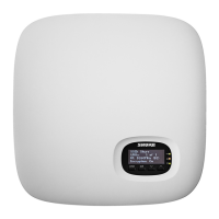
② Access Point Transceiver (APT)
•Transports encrypted, wireless audio between
the microphones and the Dante network.
•Maintains stable audio transmission through
advanced interference detection and
automatic frequency coordination.
•Requires only a single Cat5e cable for power
(via PoE), system time-sync management,
and the communication of networked audio
and control data.
•Hosts the web browser-based GUI for remote
system management.
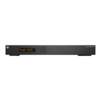
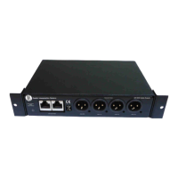
③ Audio Network Interface (ANI)
•Converts 24-bit/48k digital audio from the
network into analog direct outputs.
•Four-port gigabit switch enables the ANI to be
the networking hub of an eight-channel MXW
system.
•Network Port 4 (Uplink) can be configured
to restrict audio and provide protected data
uplink to a corporate network.
•Input channels add audio to the network for
monitoring at the microphone headphone
output.
Note: The ANI can be substituted with the Shure
SCM820 Digital IntelliMix Mixer.
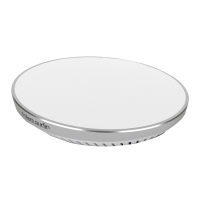
④ Networked Charging Station (NCS)
•Recharges microphone batteries by
connecting to the USB port of the microphone.
•Links up to eight microphones at a time to
channels in a group.
•Transmits detailed battery information to the
network.
•LEDs display microphone battery charge
status.
⑤ Graphical User Interface (GUI)
The MXW System is managed from the
graphical user interface (GUI). The computer
must be networked to the APT to access the
GUI from a web browser. Use the software
interface for the following system functions:
•Assign components to groups to determine
the routing of digital audio and control data.
•Perform an RF spectrum scan to accurately
survey a site's spectrum activity over a
duration of time.
•Monitor microphone battery statistics during
the charge.
•Control microphone activity state, gain setting
and EQ filters.
•Customize the function of LED and mute/
active button of the microphone.
•Configure IP settings.