18
Hardware Interface Description
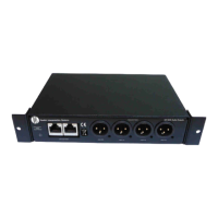
Audio Network Interface (ANI)
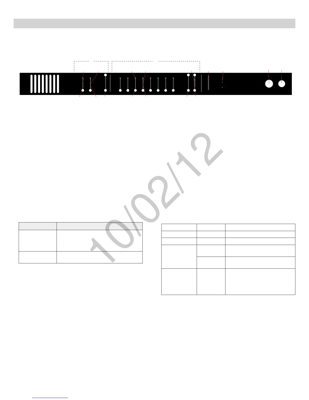
Front Panel
① Input Channels
Adds analog line- or aux-level signals to the digital network. When
associated to the APT, inputs are automatically routed to linked
microphone channels (Input A to channels 1-4; Input B to 5-8). Typical
applications include sending translated audio or a mix for personal
monitoring at the microphone headphone jack.
② Output Channels
Sends analog audio out from the digital audio network. When connected
to the MXW system, the outputs are automatically routed from the
associated MXWAPT.
③ Channel Select Button
Selects a channel and performs the following functions:
Action Function
Single Press
•Listen to the channel at the headphone jack
•Display and adjust channel gain
•
Monitoroutputsignallevelonthe⑪Level
Meter
Press and Hold (3
seconds)
Mute/unmute a channel. Mute is indicated by
the⑥MuteLED.
④ Selected Channel LED
Illuminates when a channel is selected.
⑤ Signal Strength LED (sig/clip)
Indicates audio signal strength for each channel:
Green = Normal
Amber = Strong
Red = Clipping (to eliminate clipping, attenuate the signal level at the
audio source)
⑥ Mute LED
Illuminates red when the Channel Select button is held for 3 seconds,
muting the channel. A muted channel is still routed to the HEADPHONE
jack for monitoring or troubleshooting.
⑦ Input Level Select Buttons
Set the selected channel to line- or aux-level to match the input signal.
⑧ Output Level Select Buttons
Set the selected channel to an output level that matches the connecting
device:
line: +4 dBU
aux: −10dBV
mic: −30dBV
⑨ Output Gain Control
Use the up/down buttons to adjust the channel gain attenuation from 0
dB (no attenuation) to -24 dB.
⑩ Output Gain Setting
Displays the attenuation made from the Output Gain Control.
⑪ Level Meter
Displays a selected channel’s audio level in dBFS. It is good practice to
use -18 dBFS on the output meter as an approximation of 0 VU on an
analog meter.
⑫ Hardware Status LEDs
Illuminate to indicate the status of the hardware:
power
ethernet
network audio
lockout
-18
-24
0
-6
-12
line
aux
mic
mute
sig/clip
line
aux
mute
sig/clip
Audio Network Interface
HEADPHONE
-18
-24
-30
-36
-48
-60
-9
0
INPUT OUTPUT
push to solo | hold to mute adjust
A B 1 2 3 4 5 6 7 8
③
③
④ ④⑤ ⑤
⑥
⑥
⑦ ⑧ ⑨
⑩ ⑪ ⑫
⑬ ⑭
①
②
LED Color Status
power Green Unit is powered on.
Ethernet Green Connected to an Ethernet device.
network audio
Green
Sending or receiving a digital audio
signal.
Flashing
Green
Cannot establish a connection.
lockout Red
Front panel gain and mute controls
are locked. The LED will blink when
a button is pressed while the hard-
ware is locked. A channel can still be
selected for headphone monitoring.
⑬ Headphone Volume Knob
Adjusts the volume to the headphone output.
⑭ Headphone Output
1/4” (6.35 mm) output jack for monitoring a selected channel.