17
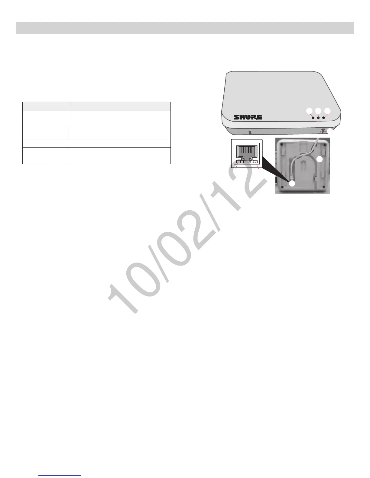
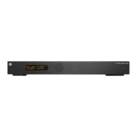
Hardware Interface Description
① Power LED
Illuminates green when Power over Ethernet (PoE) is provided.
② Network Audio LED
•Solid Green: Sending or receiving a digital audio signal.
•Flashing Green: Cannot establish a connection.
③ RF Link LED
Color Status
Green
≥1linkedmicrophoneispoweredoninthe
Active or Mute state.
Solid Yellow
≥1linkedmicrophoneisintheStandbyorOff
state.
Flashing Yellow The ID button in the GUI has been pressed.
Solid Red Problem with RF connection ???
Flashing Red No microphones are linked to the unit.
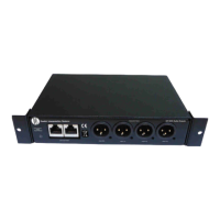
④ Reset Button
Press and hold the reset button for 10 seconds to hard reset the MXW
system to factory default settings.
Note: Performing a reset will delete system configurations made in the
GUI, including device association and microphone link.
⑤ Ethernet Jack
Connects a Cat5e (or higher) cable to a PoE source and the network.
⑥ Network Status LED (Green)
Off = no network link
On = network link established
Flashing = network link active
⑦ Network Speed LED (Amber)
Off = 10/100 Mbps
On = 1 Gbps
⑧ Cable Routing Path
Routes the Ethernet cable to enable a flush-mount to the surface.
③
④
⑤
⑥
⑦
⑧
①
②
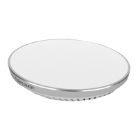
Access Point Transceiver (APT)