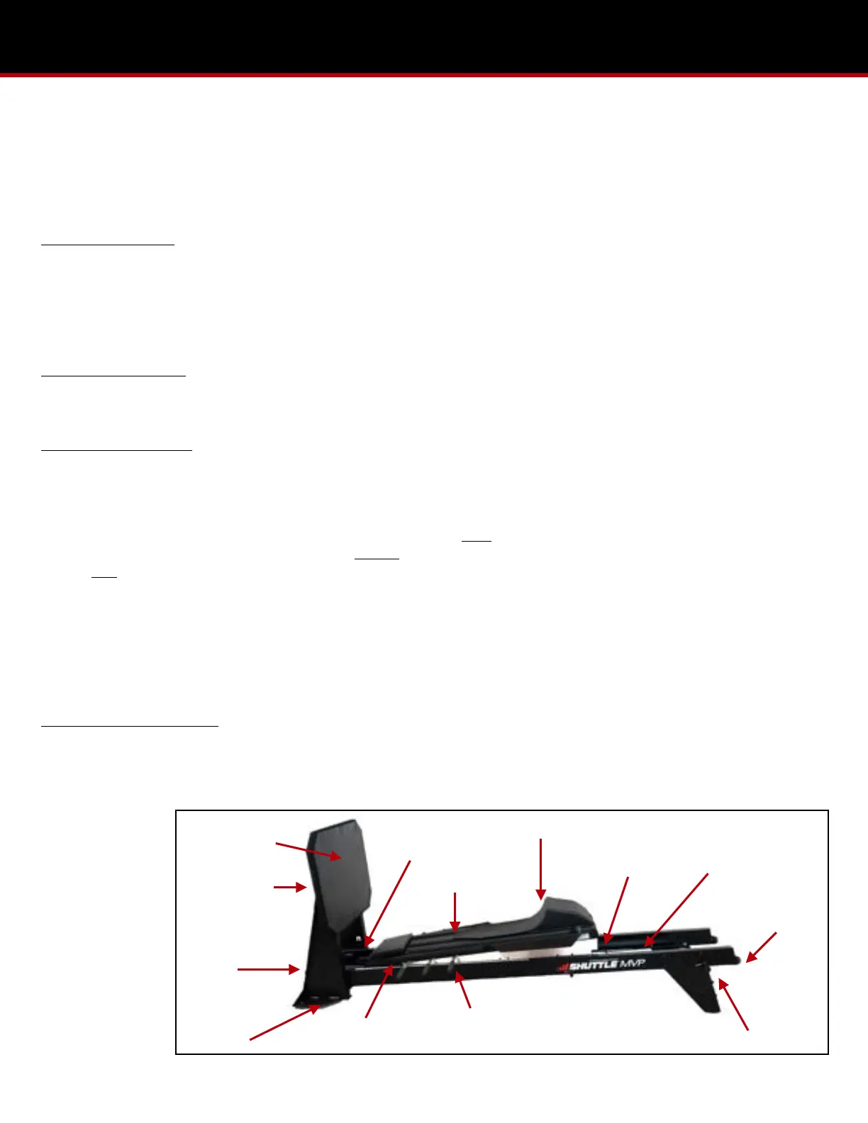
Located between the MVP rails are eight elasticords. They are at the head-end of the machine attached to the black and
red lanyards. There are also eight additional elasticords attached to the foot-end of the carriage with t-handles.
Warning!!If you grasp the lanyard too close to the!plastic white knob you risk pinching your fingers.! !
Always detach the elasticords when the machine is not in use. This prevents premature stretching of the elasticords
and greatly extends their life.
Attaching Elasticords: To engage the head-end elasticords grasp the middle of the lanyard (one at a time) and pull back
towards the head-end stand preferably using your core. Slip the exposed plastic white knob at the end of the elasticord
into at the corresponding slot at the!head-end of the carriage to engage the elasticord.
To engage the foot-end elasticords pull the black t-handle (one at a time) towards the foot-end to engage with the slotted
plate at the bottom of the kickplate structure. Engage the elasticords with lanyards before engaging the elasticords with t-
handles.
Detaching Elasticords: To disengage resistance, grasp the middle of the lanyard and pull back towards the head-end stand
and drop it down into the carriage. To disengage resistance of the elasticords with t-handles, grasp the handle and gently
pull it back towards the kickplate structure and back into the carriage.
Adjusting the Kickplate: The kickplate adjusts to three vertical positions. To adjust the height, begin by removing the four
knurled knobs from the back of the kickplate. Move the kickplate board to the desired vertical position. Line up the bolts on
the back of the kickplate board with the appropriate holes in the kickplate structure and secure by tightening the four
knurled knobs down.
The vertical position of the kickplate can be positioned as follows: High- This is the best position for 90 degree flexion of
taller individuals and unsupported heel activities. Middle- Majority of users will enjoy this position to achieve 90 degree
flexion. Low- This position is best for direct body alignment activities.
The headrest is easily adjusted depending on patient size and desired exercise type. This can be done by pulling the
headrest up and away from the backrest and repositioning with the velcro strips.
The footrest is located at the end of the carriage. It provides a surface to rest an uninvolved foot. It can be covered with the
butt pad provided to accommodate small adults or children.
Adjusting the ROM Control: At the head-end of the carriage is a ROM control handle. The handle may be pulled forward
and secured in any of the three
positions at the head-end stand. Moving the ROM handle down the surface of the head-end stand draws the carriage
head-ward up the rails. This adjustment will decrease the angle of knee flexion.
Warning! Never
attempt to move
the ROM handle
while the elasticords
are attached or the
machine is in use,
as the handle may
move too quickly
to control.