O P E R A T I N G I N S T R U C T I O N S e n
All rights reserved. Subject to change without notice.
1 About this document
Read these operating instructions carefully before you mount and commission the
Encoder.
1.2 Purpose of this document
These operating instructions provide qualified technical personnel of the machine
manufacturer or the machine operator with instructions regarding the mounting,
electrical installation, commissioning, operation, and maintenance of the
encoder.
2 Safety information
AHS/AHM36 IO-Link and AHS/AHM IO-Link Inox absolute encoders are manufac‐
tured using state-of-the-art technology.
The encoders should only be mounted by qualified personnel with electrical
and precision engineering knowledge.
The encoder may only be used for the purpose for which it was intended.
2.2 General safety notes
Observe the relevant national work safety regulations as specified by trade
associations.
During mounting, disconnect all applicable devices, machinery and systems
from the voltage.
Never connect or disconnect electrical connections to or from the encoder
when the voltage is switched on, as this may result in equipment damage.
Prevent any impact to the shaft and collet.
3 Mounting
3.1 Encoder with servo flange
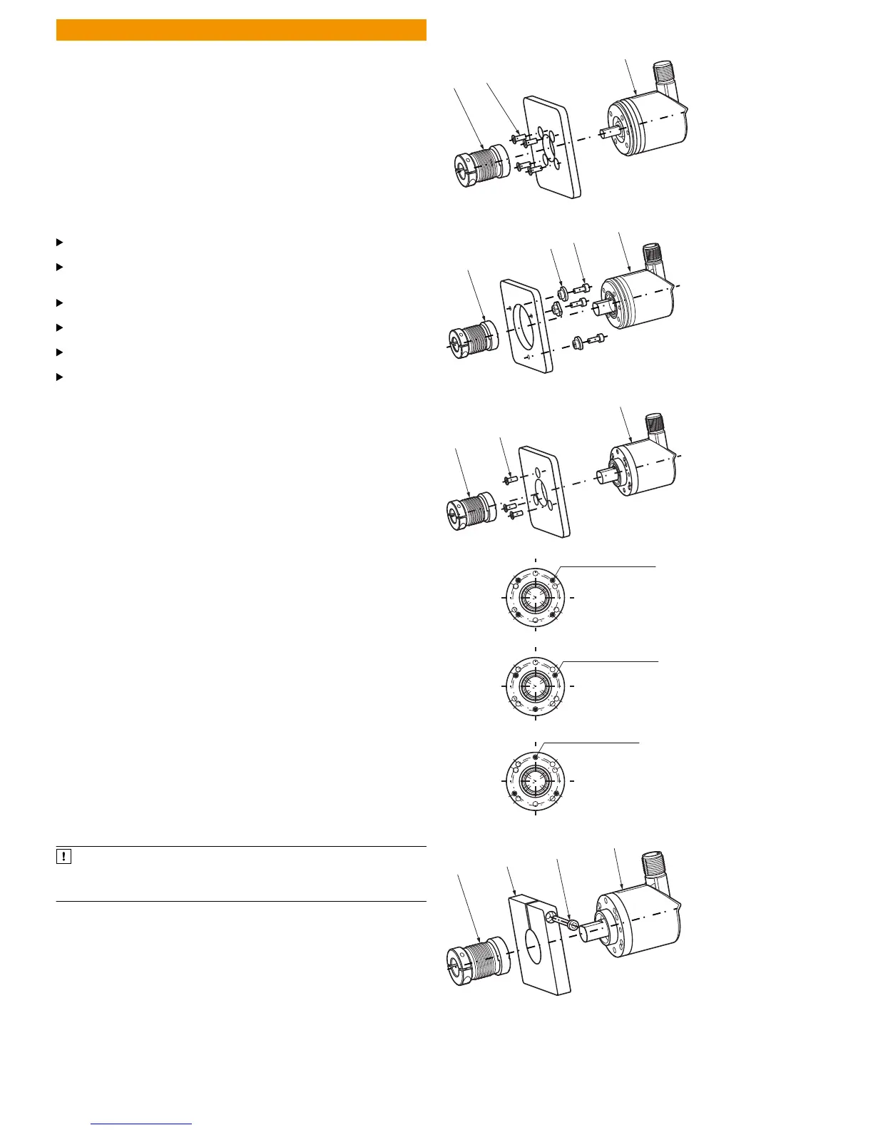
3.1.1 Mounting via threaded holes on the flange side (Fig. 1)
Block the customer’s drive shaft. Mount the coupling (1) on the encoder (2);
ensure that this does not touch the encoder flange. Slide the encoder (2) together
with the mounted coupling (1) onto the drive shaft. Mount the encoder (2) using
four M3 screws (3). Mount the coupling (1) on the drive shaft. Ensure that the
coupling is not subjected to any axial stress. Establish an electrical connection
when the voltage is switched off. Switch on the voltage and check that the
encoder is functioning.
3.1.2 Mounting with servo clamps (Fig. 2)
Block the customer’s drive shaft. Mount the coupling (1) on the encoder (4);
ensure that this does not touch the encoder flange. Mount servo clamps (2) using
M3 screws (3). Do not tighten the screws; twist the servo clamps in such a way
that the encoder flange can be pushed into the center. Slide the encoder (4)
together with the mounted coupling (1) onto the drive shaft and center.
Engage the servo clamp (2) by rotating it into the slot and tighten it slightly. Mount
the coupling (1) on the drive shaft. Ensure that the coupling is not subjected to
any axial stress. Tighten all three screws on the servo clamps. Establish an electri‐
cal connection when the voltage is switched off. Switch on the voltage and check
that the encoder is functioning.
3.2 Encoder with face mount flange
There are two mounting options for this type of flange:
•
Via the threaded holes on the flange side
•
By clamping on the mounting spigot
3.2.1 Mounting via threaded holes on the flange side (Fig. 3)
Mount coupling (1); ensure that it does not touch the encoder flange. Slide the
encoder (2) together with the mounted coupling (1) onto the drive shaft and the
centering fixture/mounting spigot. Mount the encoder (2) using three M3 screws
(3) and mount the coupling (1) on the drive shaft. The coupling must not be sub‐
jected to any axial stress. Establish an electrical connection when the voltage is
switched off. Switch on the voltage and check that the encoder is functioning.
3.2.2 Mounting via the mounting spigot (Fig. 4)
NOTICE
Since the mounting spigot is also a centering lug, the clamping device must
be designed so that no prohibited angles or shaft misalignments are made
during the clamping process.
Block the customer’s drive shaft. Mount the coupling (1); ensure that it does not
touch the encoder flange when twisting the shaft. Slide the encoder (4) together
with the mounted coupling (1) onto the drive shaft and mounting spigot into the
clamping device (2). Clamp the encoder (4) with a screw (3). Mount the cou‐
pling (1) on the drive shaft.
The coupling must not be subjected to any axial stress. Establish an electrical
connection when the voltage is switched off. Switch on the voltage and check that
the encoder is functioning.
3.3 Encoder with flange for blind hollow shaft (Fig. 5 and 6)
Block the customer’s drive shaft. Loosen cylinder head screw (2) on the clamping
ring (1). Slide the encoder together with the collet onto the drive shaft. Take note
of the mounting information in Fig. 6! Mount the stator coupling (3) using two M3
screws (4) and washers (5). Loosen cylinder head screw (2) on the clamping ring
(1).
Max. tightening torque 0.8 Nm.
Establish an electrical connection when the voltage is switched off. Switch on the
voltage and check that the encoder is functioning.
 Loading...


