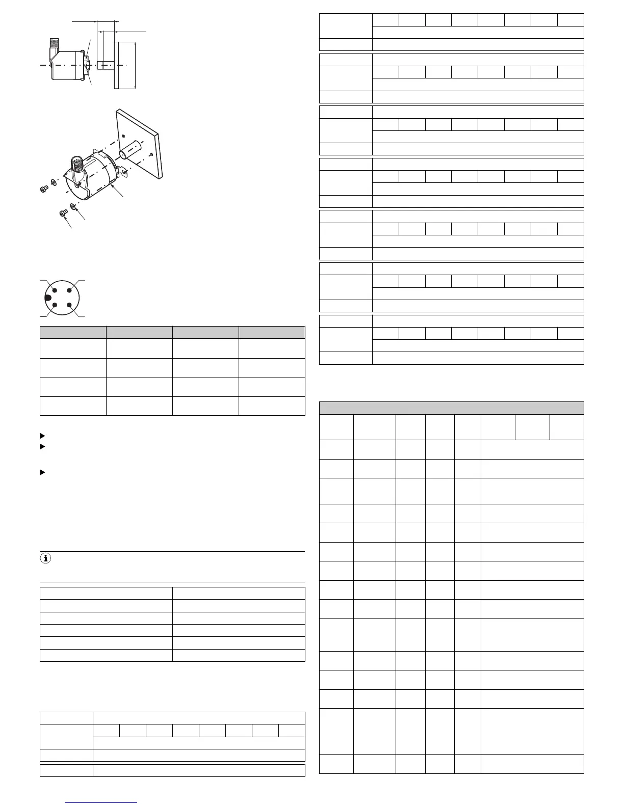
PIN Wire color Signal Function
1 Brown L+ Encoder supply volt‐
age 20 - 30 V (+U
S
)
2 White I/Q not connected - no
function
3 Blue L- Encoder supply volt‐
age 0 V (GND)
4 Black C/Q IO-Link communica‐
tion
4.2 Connecting the device electrically
Connect directly via M12 round screw system or cable outlet.
The rotatable male connector / cable outlet is intended only for aligning the
male connector / cable outlet during mounting, not for permanent move‐
ment.
The enclosure rating for the connector outlet can only be achieved with the
mating connector screwed into place.
Tightening torque for the mating connector at an M12 connector outlet: 1.0 Nm
4.3 IO-Link specific information
Download the IODD file for the AHS36/AHM36 IO-Link or AHS/AHM36 IO-Link
Inox from www.sick.com or from the IODD-Finder of the IO-Link Consortium. Make
sure to always use the most current IODD file.
4.3.1 Physical layer
NOTE
Maximum current consumption of the IO-Link device (including load currents)
must not exceed the maximum output current of the master port.
SIO mode No
Min. cycle time 3.2 ms
Baud rate
1
COM3
Process data length 8 bytes
IODD version V 1.0
Valid for IO-Link version 1.1.0
1
COM values specify the baud rate (see IO-Link specification): COM1 (4.8 kbps), COM2
(38.4 kbps), COM3 (230.4 kbps)
4.3.2 Process Data
Record: 8 bytes
Byte offset
Byte 0 63 62 61 60 59 58 57 56
Velocity
Type/Subindex Integer 32
Byte offset
Byte 1 55 54 53 52 51 50 49 48
Velocity
Type/Subindex Integer 32
Byte offset
Byte 2 47 46 45 44 43 42 41 40
Velocity
Type/Subindex Integer 32
Byte offset
Byte 3 39 38 37 36 35 34 33 32
Velocity
Type/Subindex Integer 32
Byte offset
Byte 4 31 30 29 28 27 26 25 24
Position
Type/Subindex Unsigned integer 32
Byte offset
Byte 5 23 22 21 20 19 18 17 16
Position
Type/Subindex Unsigned integer 32
Byte offset
Byte 6 15 14 13 12 11 10 9 8
Position
Type/Subindex Unsigned integer 32
Byte offset
Byte 7 7 6 5 4 3 2 1 0
Position
Type/Subindex Unsigned integer 32
4.3.3 Service data
The following ISDUs are not backed up by data storage: device-specific marking
and raw position value.
IO-Link specific
Index
decimal
(hex)
Name Format
(Offset)
Length Access
1
Default
value
Value
range
Remark
[unit]
0 (0x00) Direct para‐
meter 1
Record 16 byte
s
rw see IO-Link interface specification
1 (0x01) Direct para‐
meter 2
Record 16 byte
s
rw see IO-Link interface specification
12 (0x0C) Device
Access
Locks
Record 2 bytes rw
2
(0x02)
Data Storage
Lock
Bit (1) 1 Bit rw
16 (0x10) Vendor name String 64 byte
s
ro SICK AG
17 (0x11) Vendor text String 64 byte
s
ro SICK Sensor Intelligence
18 (0x12) Product
Name
String 64 byte
s
ro AHx36x-xxxxxxxxxx
19 (0x13) Product ID String 64 byte
s
ro 1xxxxxx
20 (0x14) Product text String 64 byte
s
ro Absolute Encoder Multiturn
21 (0x15) Serial Num‐
ber
String 16 byte
s
ro yywwnnnn
y = year
w = week
n = counter
22 (0x16) Hardware
Version
String 64 byte
s
ro 1.0
23 (0x17) Firmware
version
String 64 byte
s
ro 1.1.0
24 (0x18) Application
Specific Tag
String 32 byte
s
rw Application-specific marking,
writable by user
36 (0x24) Device Sta‐
tus
UInt 8 bits ro 0 = Device is OK
1 = Maintenance required
2 = Out of specification
3 = Functional check
4 = Failure
5 ... 255 = Reserved
40 (0x28) Process
Data Input
PD in 8 bytes ro As described in chapter Process
Data, but acyclic
1
ro = read only, wo = write only, rw = read/write
8022049/2018-02-14/de, en AHS/AHM36 IO-Link AHS/AHM36 IO-Link Inox | SICK 6
 Loading...


