6.6 PIN assignment
CDB620-101
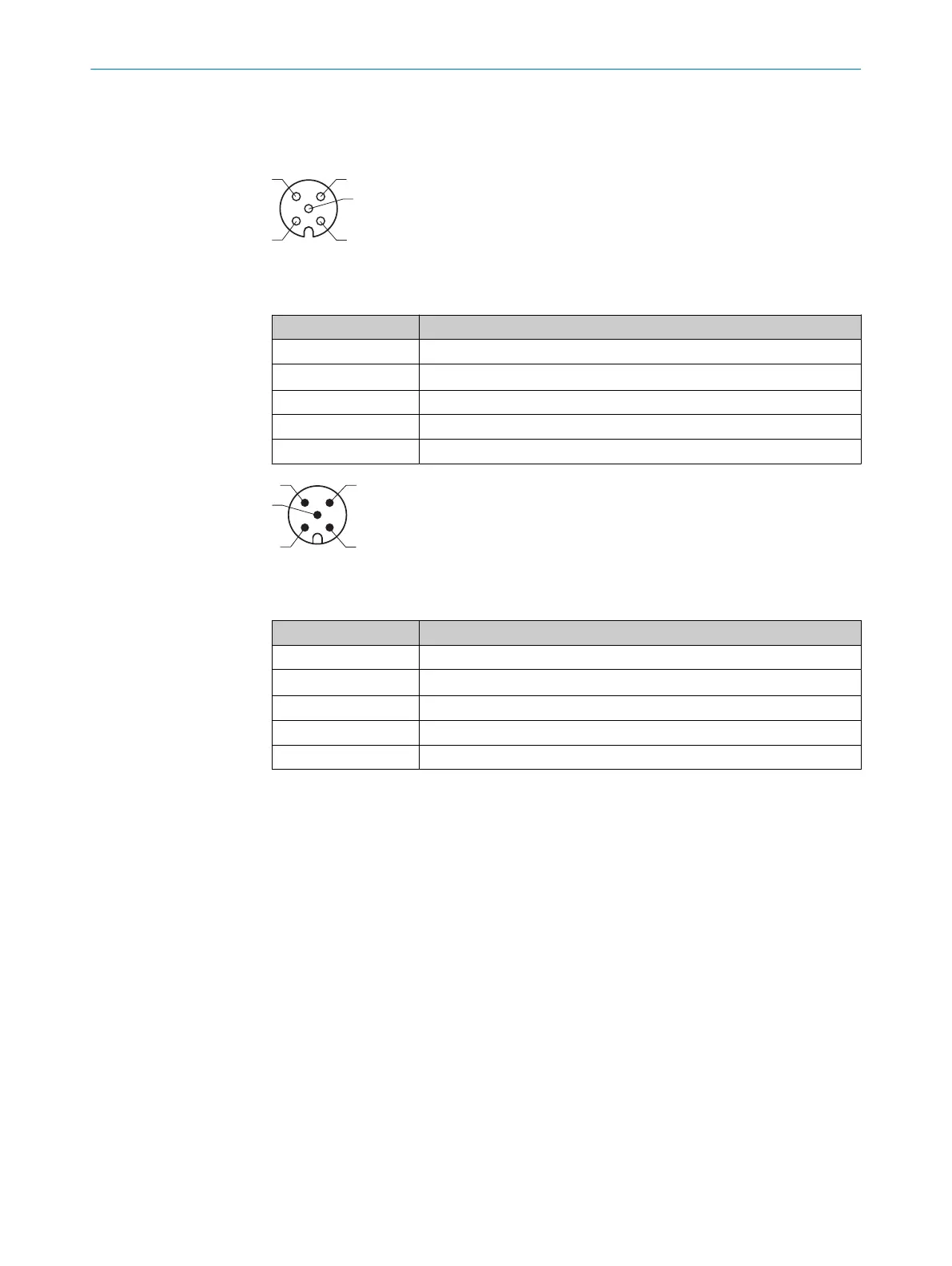
Figure 5: CAN bus
Table 2: Female connector, M12, 5-pin, A-coded
PIN Signal
1 Screen
2 V
S
3 GND
4 CAN H
5 CAN L
Figure 6: CAN bus
Table 3: Male connector, M12, 5-pin, A-coded
PIN Signal
1 Screen
2 V
S
3 GND
4 CAN H
5 CAN L
6 ELECTRICAL INSTALLATION
18
O P E R A T I N G I N S T R U C T I O N S | CDB620 8021690/ZZN1/2021-05-07 | SICK
Subject to change without notice