3 Product description
•
Module for connecting an ID sensor
•
Base module for accommodating an optional CMC600 (Connection Module Clon‐
ing) for external storage of ID sensor configuration parameters. Also used to
activate operating modes and to extend the ID sensor by two digital switching
inputs and two switching outputs (for CLV61x to CLV65x, Lector620, RFH6xx and
RFU62x)
•
Internal 9-pin D-Sub male connector: for connecting the AUX interface (serial
RS-232) to a computer for ID sensor configuration and diagnostics
•
Terminals for serial host interface, CAN bus (CDB620-101: 2x M12 plug connec‐
tions), switching inputs and switching outputs, voltage supply, shielding
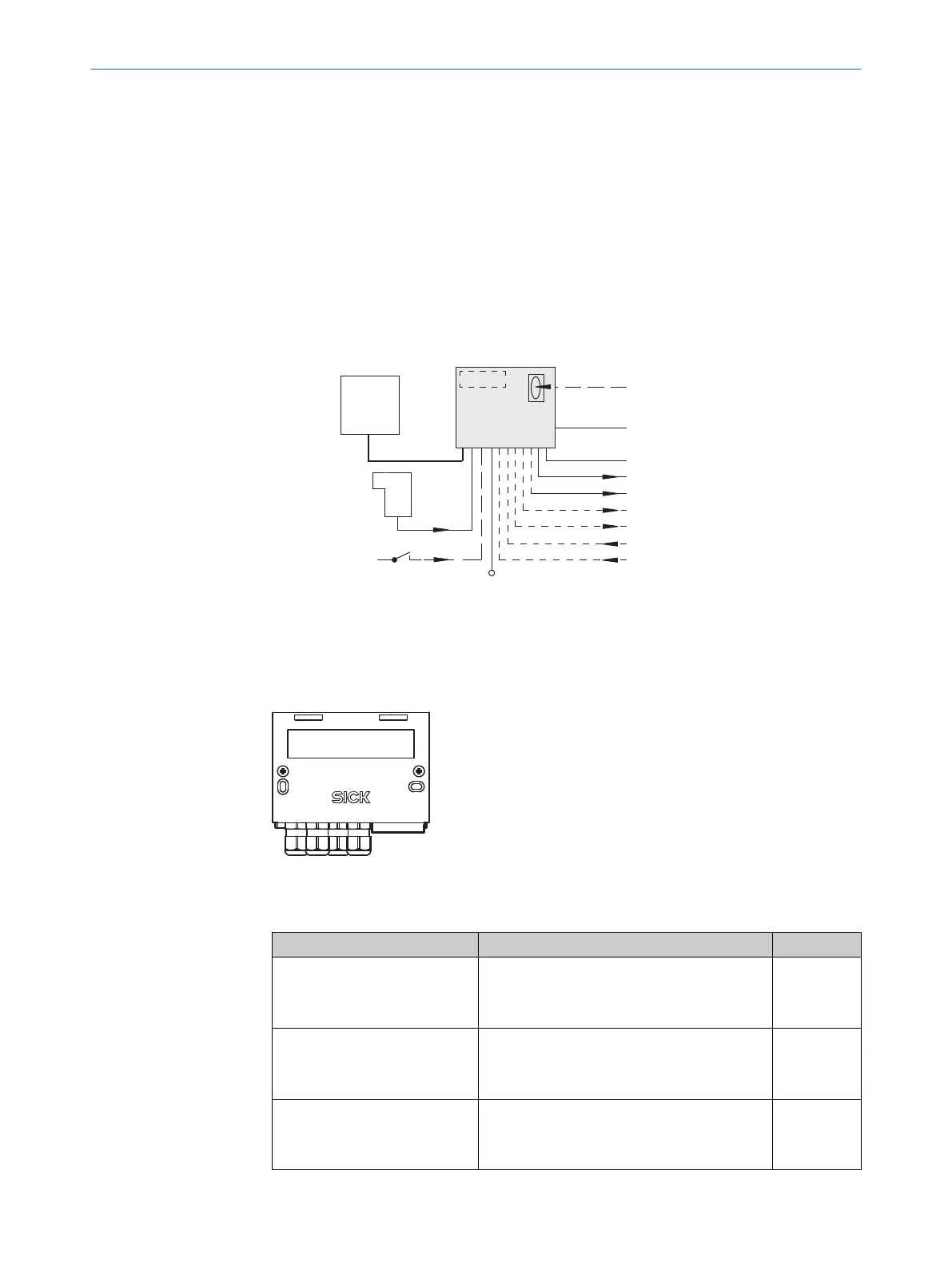
“Sensor 2”
“Host”
V
S
“Sensor 1”
“Result 1”
“Aux”
PC
HOST
SPS/PLC
ID
Sensor
CDB620
. . . .
. . . . .
“CAN”
CAN bus
“Result 2”
SPS/PLC
CMC600
“Out 1”
“Out 2”
“In 1”
“In 2”
1
2
1
Photoelectric sensor (read cycle)
2
Switch
3.1 Configuration elements and displays
1
LED display with label
Function of the configuration switches
Switch Function Default
S 1 (Power) Supply voltage applied:
•
ON: Supply voltage on
•
OFF: Supply voltage off
ON
S 2 (TermCAN) CAN bus termination:
•
ON: 120 Ohm resistor connected
•
OFF: no termination
OFF
S 3 (SGND-GND) Reference potential for sensor GND:
•
ON: Connected to GND of the ID sensor
•
OFF: Volt-free
OFF
PRODUCT DESCRIPTION 3
8021690/ZZN1/2021-05-07 | SICK O P E R A T I N G I N S T R U C T I O N S | CDB620
9
Subject to change without notice