9 Technical data
NOTE
The relevant online data sheet for your product, including technical data, dimensional
drawing, and connection diagrams can be downloaded, saved, and printed from the
Internet:
•
www.sick.com/CDB
Please note: This documentation may contain further technical data.
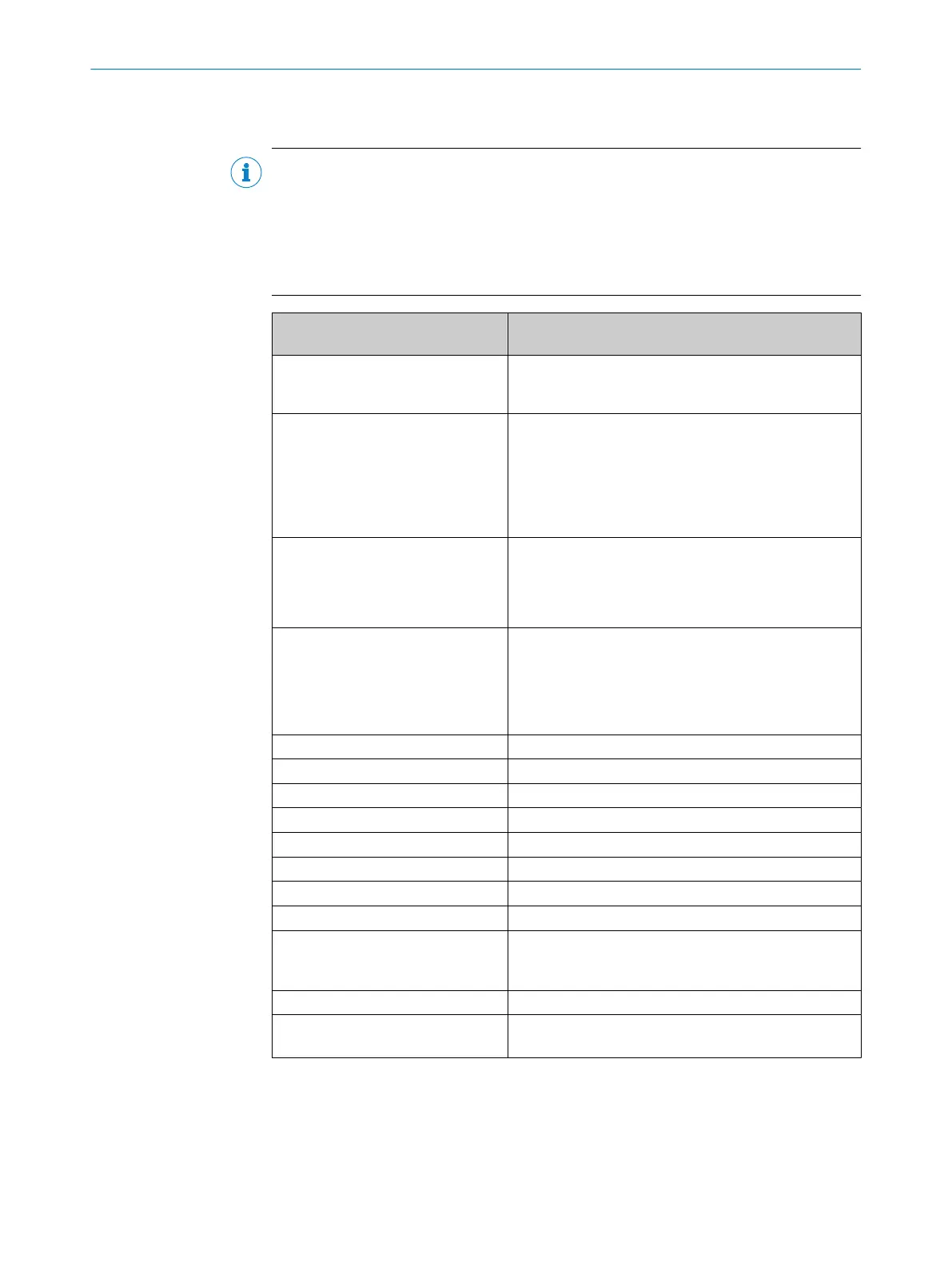
Type CDB620-001 (no. 1042256), CDB620-101 (no.
1042257), CDB620-201 (no. 1042258)
Optical indicators 9 x LED for displaying active switching inputs and switch‐
ing outputs as well as the configured switch positions of
the module (visible through the cover)
Electrical connections Female connector, D-Sub-HD, 15-pin/male connector,
D-Sub, 9-pin (CDB620-101: additional male/female con‐
nector, M12, 5-pin, A-coded for CAN bus)
Spring-loaded terminals:
•
8 for 0.14 mm
2
... 2.5 mm
2
wires
•
24 for 0.14 mm
2
... 1 mm
2
wires
Cable glands (clamping range ∅ 4.5 mm ... 10 (7) mm)
•
CDB620-001: 4 x M16
•
CDB620-101: 2 x M16
•
CDB620-201: 4 x M16, 1 x M12
Supply voltage DC 10 V... 30 V, SELV or PELV according to
IEC 60364-4-41.
Use one of the following power supply units:
•
UL60950-1: LPS or Class 2 (UL1310)
•
UL508: Class 2 (UL1310)
Power consumption 1 W
Input current Max. 2.4 A
1)
Fuse
2)
Glass tube fuse, 0.8 A slow blow
Housing Polycarbonate
Mark of conformity CE, UL
3)
Electrical safety IEC 61010-1:2010 + Cor.: 2011
Protection class III according to EN 61140
Enclosure rating IP65
4)
according to EN 60529
EMC test Radiated emission: according to EN 61000-6-3: 2007-
01/ A1: 2011-03
Shock resistance: according to EN 61000-6-2: 2005-08
Weight Approx. 260 g
Ambient temperature Operation: –35 °C ... +40 °C
5)
Warehouse: –35 °C ... +70 °C
TECHNICAL DATA 9
8021690/ZZN1/2021-05-07 | SICK O P E R A T I N G I N S T R U C T I O N S | CDB620
21
Subject to change without notice