8014868/YIF1/2020-10-19 • © SICK AG • Subject to change without notice 17
Design and function
4 Design and function
4.1 Structure
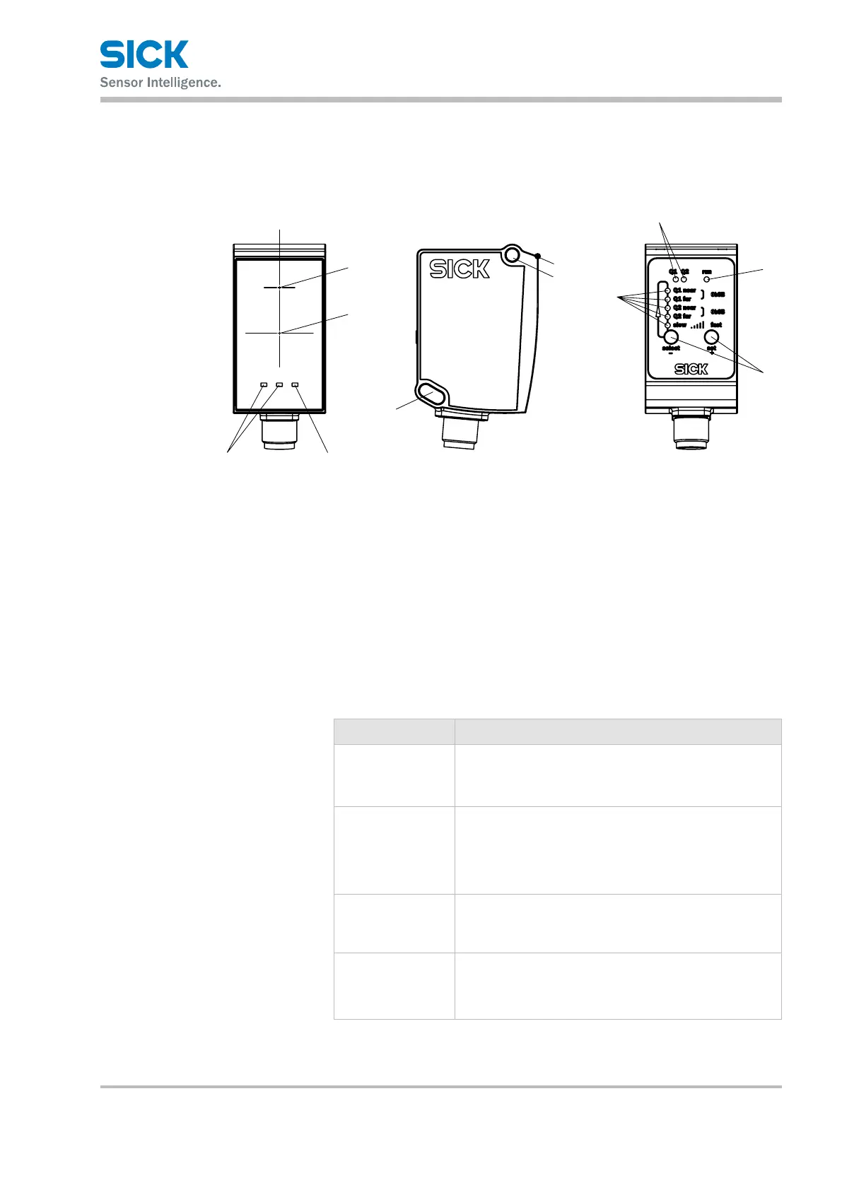
Fig. 5: ”Dx35 distance sensor” structure and function
1 Optical axis, sender
Laser output aperture corresponds to the front screen at the height of the
position shown.
2 Optical axis, receiver
3 Reference surface ( corresponds to 0 mm)
4 M4 xing hole
5 Teach-in LEDs
6 Q1/Q2 status LEDs
7 Status indicator LED
8 Operating pushbuttons
Q1 and Q2 status LEDs (continued on
next page)
LED Description
Q1 Q1 switching output indicator
• Orange LED: switching output active
• LED o: switching output inactive
Q2 Q2 switching output/Qa analog output indicator
• LED orange: Switching output active/measured value
within analog output scaling
• LED o: Switching output inactive/measured value
outside analog output scaling
Q1 and Q2
in run mode
• "Q1" and "Q2" LEDs ash alternately for longer than 10
seconds: fault exists. Check general conditions such as
supply voltage, temperature range, EMC disturbances,
etc.
Q1 and Q2
in teach mode
• "Q1" and "Q2" LEDs ash simultaneously: teach is being
performed.
• "Q1" and "Q2" LEDs ash alternately for 5 seconds:
teach failed.
 Loading...


