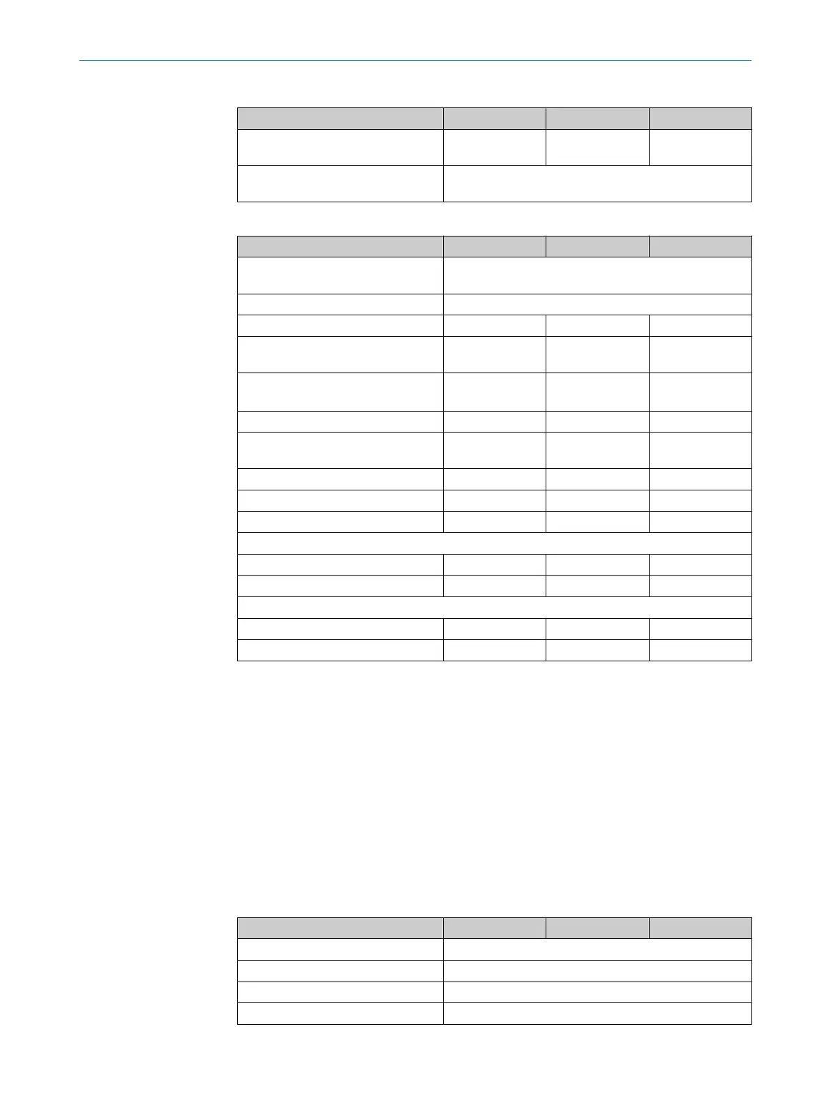
Table 10: Technical data for sender
Minimum Typical Maximum
Wavelength of sender Near-infrared
(NIR
), invisible
Weight Depending on the protective field height, see "Table of
weights", page 54
Table 11: Technical data for receiver
Minimum Typical Maximum
Output signal switching devices
(OS
SDs)
2 PNP semiconductors, short-circuit protected
1)
, cross-
circuit monitored
Response time "Response time", page 53
Duration of OFF state 100ms
Switch-on delay 3 × response
t
ime
ON state, switching voltage HIGH
(U
rms
)
2)
U
V
– 2.25V 24V U
V
OFF state, switching voltage LOW
2)
3)
0V 0V 2.0V
Current-carrying capacity of the
O
SSDs
300mA each
Leakage current of the OSSDs 2mA each
Load capacity 2.2µF
4)
Load inductance 2.2H
Test pulse data
5)
Test pulse width 150µs
6)
300 µs
6)
Test pulse rate 3s
-1
5s
-1
10s
-1
Permissible cable resistance
7)
Supply cable
8)
1Ω
Cable between OSSD and load 2.5Ω
1)
Applies to the voltage range between -30V and +30V.
2)
According to IEC 61131-2.
3)
The specified values are the switching voltage supplied by the safety light curtain. If higher voltages are
im
planted externally, the maximum value of 2.0V can be exceeded.
4)
Applies to devices marked “(Rev. 1)” on the “Ident No.” type label entry. For devices not marked “(Rev.
1)”, the following applies: Load capacity (maximum) = 30nF.
5)
When active, the outputs are tested cyclically (brief LOW). When selecting the downstream controllers,
make sure that the test pulses do not result in deactivation when using the above parameters.
6)
Applies to devices marked “(Rev. 1)” on the “Ident No.” type label entry. For devices not marked “(Rev.
1)”, the following applies: Test pulse width (typical) = 300µs; test pulse width (maximum) = 350µs.
7)
Limit the individual conductor resistance to the specified values to ensure that the light curtain func‐
tions correctly, particularly that a cross-circuit between the outputs is safely detected. (Also observe
IEC60204-1.)
The specified values apply to the total resistance of each wire including contact and connector resistan‐
ces.
8)
The supply cable must not be used to connect other loads with the exception of the senders.
Table 12: Operating data
Minimum Typical Maximum
System connection 5-pin M12 male connector
Length of cable 150mm
Cable diameter 4.3mm
Cable material PVC
12 TECHNICAL DATA
52
O P E R A T I N G I N S T R U C T I O N S | deTec4 Core Vibes 8024467/1GWF/2022-11-11 | SICK
Subject to change without notice
 Loading...


