6 Electrical installation
6.1 Safety
DANGER
H
azard due to electrical voltage
Death or severe injury
b
Make sure that the machine and the connecting cables of the safety locking
device are and remain disconnected from the power supply during the electrical
installation.
DANGER
Incor
rect safety locking device connection
Loss of safety function
b
With insulation material or connection slots, pay attention to the temperature
resistance and mechanical load capability.
b
If different voltages are used between the contact pairs and the magnet coil (e.g.
230 V and 24 V), when wiring in the terminal compartment, make sure safe sepa‐
ration is always present.
b
For safety functions, use only safe contacts for locking device monitoring and door
monitoring.
6.2 Pin assignment
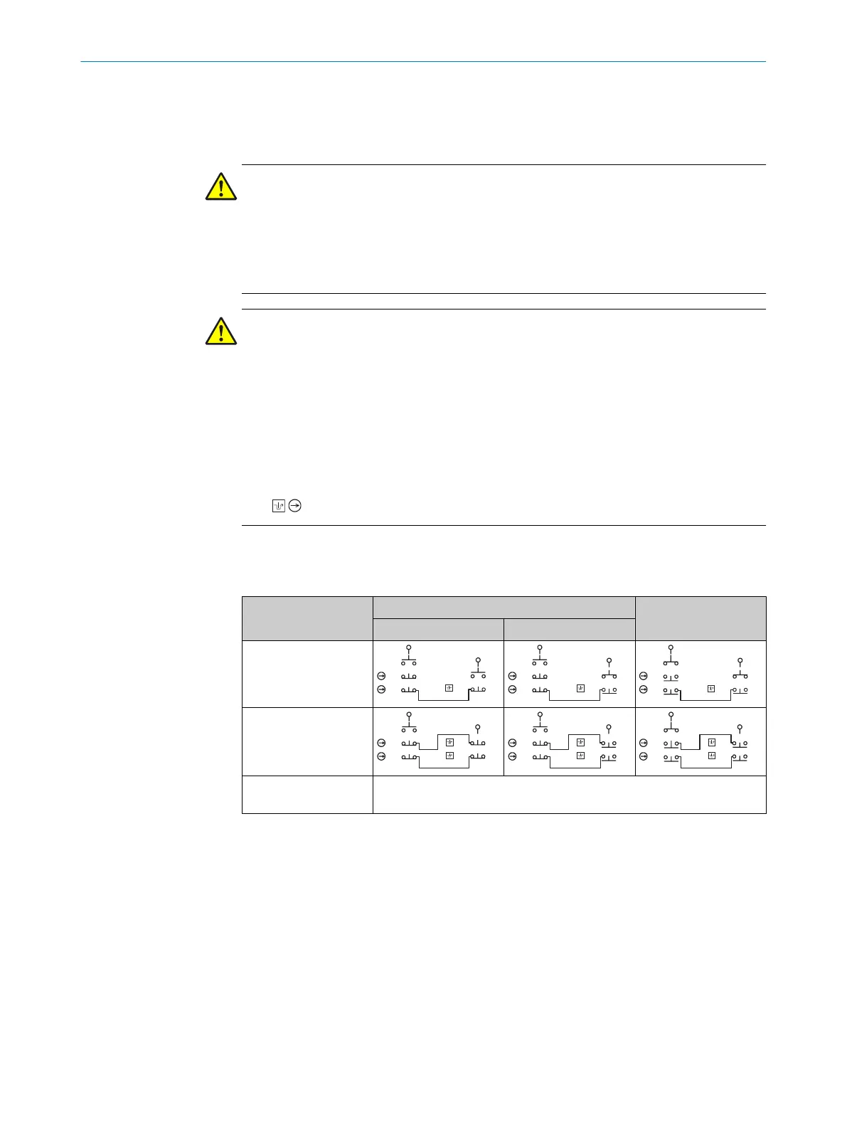
Table 3: Switching elements and switching functions
Actuator inserted Actuator removed
Locked Unlocked
i200-*02332
i200-M0413
2)
All variants E1: +24 V DC magnet coil voltage supply (locking device)
E2: +0 V DC magnet coil voltage supply (locking device)
1)
The bridge between contacts 12 and 41 must be removed to in order to enable locking device and door
monit
oring.
2)
The bridges between contacts 12 and 41 and 22 and 51 must be removed to in order to enable locking
device and door monitoring.
6.3 System connection (cable entry)
1. Open desired insertion opening with a suitable tool.
2.
Mount the cable gland with corresponding enclosure rating.
3. Connect contacts (contact assignment see table 3).
°
Connect all live contacts to one side of the contact block.
°
Operate all contact pairs and the magnet coil in the same voltage range.
°
Protect the magnet coil separately.
°
Tighten terminals to 1.0 Nm.
6 ELE
CTRICAL INSTALLATION
16
O P E R A T I N G I N S T R U C T I O N S | i200 Lock 8020558//2017-02-14 | SICK
Subject to change without notice