Reference Manual Chapter 5
Ranger E/D
©SICK AG • Advanced Industrial Sensors • www.sick.com • All rights reserved 43
Configuring Ranger E and D
5.3 Different Triggering Concepts
Different application types require different trigger concepts. Below is a table of the most
common triggering situations.
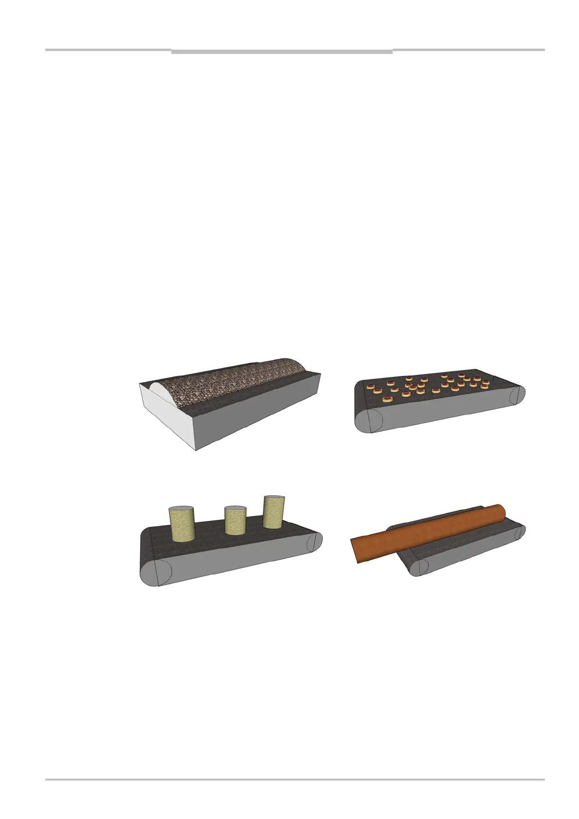
(a) Continuous flows No photoelectric switch is used.
Single scans sent continuously to the PC
Examples: Crushed stone, grain, saw dust
(b) Continuous flow of
discrete objects
No photoelectric switch is used.
Single scans sent continuously to the PC
Resulting image buffer in PC can be analyzed as overlapping
images ensuring that all objects are analyzed completely
Example: Cookies
(c) Objects of equal
length
Photoelectric switch is used.
One image per object
Examples: Bottles, automotive parts, mobile phones
(d) Objects of variable
size
Photoelectric switch is used.
Acquire scans as long as the object remains in front of the
camera
Several sub-images can be stitched together in PC
Examples: Logs, fish, postal packages
(a) Continuous flow
(b) Continuous flow of discrete objects
(c) Objects of equal length
(d) Objects of variable size
Figure 5.3 – Trigger for different object types
5.4 Enable Triggering
The Enable input is used to trigger the camera to start profile capture when the object
passes a photoelectric switch. If the same photoelectric switch is connected to several
cameras then synchronization at the microsecond level can be achieved.
When using the Enable input, the Scan height parameter specifies the number of scans
that the Ranger should make after the Enable signal goes high. After the specified number
of scans, the Ranger will either idle or continue to make another series of scans, depend-
ing on the state of the Enable signal and the setting of the Use enable parameter: